JAPANESE MINKA XXIX - BEAM FRAMING 3

Continuing with our examination of longitudinal beams (ji-mune 地棟) in Japanese roof framing (koya-gumi 小屋梁), recall from last week’s post that these beams are called nakabiki-bari (中引梁) when they run above the raised floor zashiki part of the dwelling, and ushi-bari (丑梁) when they run above the earthen-floored doma part of the dwelling. As can be seen in the diagram below, both nakabiki-bari and ushi-bari bear on the large-section daikoku-bashira internal post, at the boundary between zashiki and doma.

At its other end, the ushi-bari may be supported on an large-section ushi-mochi-bashira (丑持 lit. ‘ushi-bearing post’), not shown in the diagram, in the plane of the gable-end external wall. However, because such an oversized post doesn’t ‘fit in’ with the other posts in the gable-end wall, many minka opt for another solution, which is to erect two posts of normal size, with a beam known as a tenbin-bari (天秤梁, lit. ‘balance/scale beam’) between them, and support the ushi-bari on this beam.

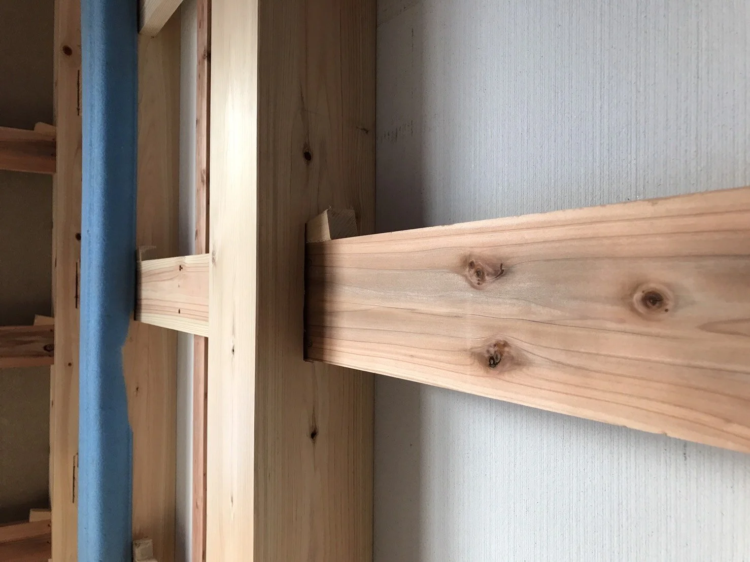
A longitudinal beam (ji-mune) supported on a short, deep balance beam (tenbin-bari) tenoned into two posts in the plane of the gable wall.

Photograph showing a) balance beam (tenbin-bari), b) longitudinal beam (ji-mune), and c) ridge pole (muna-gi).

In the Minо̄ and Tо̄hoku regions, there is a beam framing method known as torii-gumi (鳥居組, lit. torii framing), in which posts directly below longitudinal beams are omitted, and all longitudinal beams are supported on tenbin-bari. From the Kansai region west, there are many examples of large minka where ushi-bari are not especially large; instead, a number of beams of uniform size are placed at around 1 ken (1.8 metre) centres and supported on a long tenbin-bari.

Multiple bent ushi-bari bearing on a long beam at right.

As the spans get larger, the beam framing becomes progressively more complex; it is the skilful exploitation of bent or arched beams, and the free, improvised, or ‘emergent’ assembly and interlacing of them into strong structural forms, that is so characteristic of minka beam framing.

On the left, a simple longitudinal beam (ji-mune 地棟) framing system, with a single central ji-mune (either a nakabiki-bari 中引梁 or an ushi-bari 丑梁) supporting a single layer of continuous-span transverse beams (koya-bari 小屋梁). On the right, a more complex system where in addition to the koya-bari there is a lower layer of transverse beams called shiki-bari (敷梁, lit. ‘spreader beam’) or uke-bari (受梁 lit. ‘receiving beam’), tenoned into the posts, that support intermediate longitudinal beams (either ushi-bari or tobihari 飛梁).

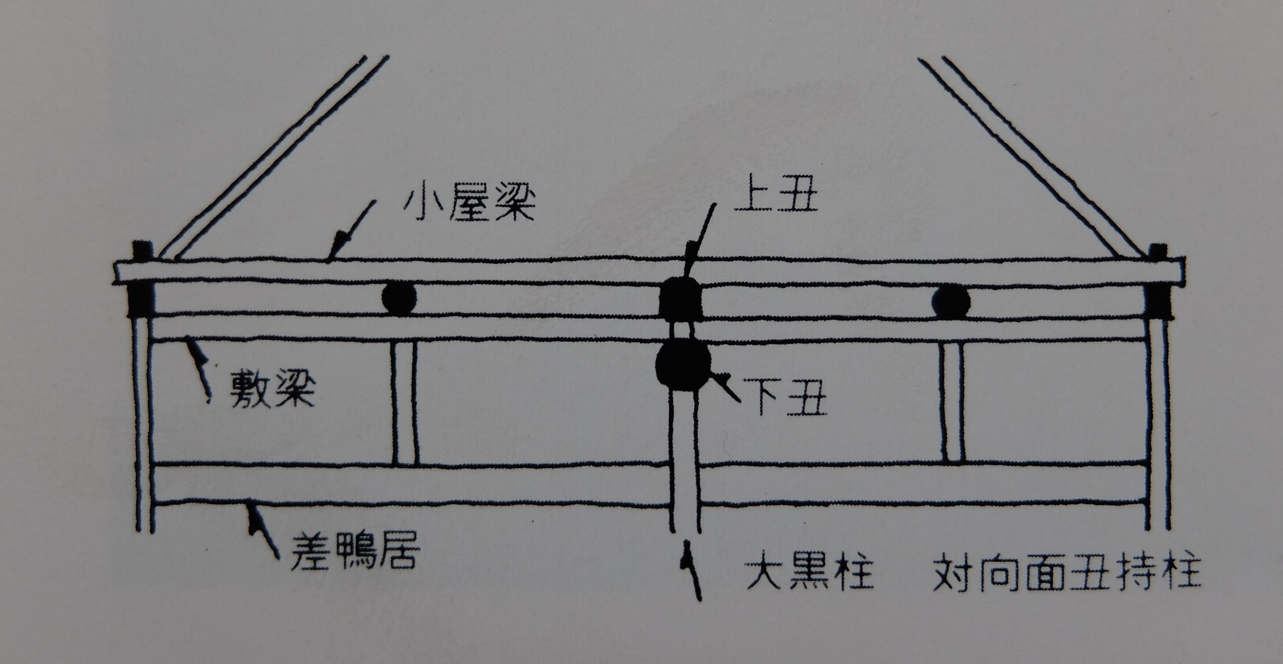
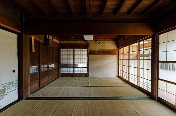
A framing system with two layers of transverse beams, as in the previous example, and two layers of longitudinal beams: the ue-ushi or uwa-ushi (上丑, lit. ‘upper ox (beam)’) and shita-ushi (下丑, lit. ‘lower ox (beam)’). The lowest transverse ‘beams’ are sashi-kamoi (差鴨居), head rails with grooved soffits to receive sliding room partitions.

A framing system with a tenbin-bari (天秤梁) supported on twin posts, and supporting the central longitudinal beam (here labelled as an ushi-bari (丑梁), indicating that it runs over the earth-floored doma part of the minka. Riding on the ushi-bari are inclined beams called nagekake-bari (投掛梁, lit. ‘throw beam’) or agari-ki (上り木, lit. ‘rising timber’). Lower tenoned beams called tsunagi-bari or tsuna-bari (繋梁, lit. ‘tie beam’) tie the inner and perimeter posts together.

Photograph showing a balance beam (tenbin-bari) supported on two posts, and supporting a (ji-mune) and two inclined beams (nagekake-bari or agari-ki). This example differs from the one shown in the section diagram above in that the tenbin-bari sits on the heads of the posts rather than being tenoned into their sides, and the nagekake-bari do not bear on the ji-mune and terminate short of it rather than being joined above it; they are supported only on the tenbin-bari.

In the minka of the mountainous areas of Hirano and surrounding districts in the Kantо̄ region, the custom was to use especially bent and twisted beams, perhaps partly because local conditions made it difficult to get hold of large, good quality pine logs, partly out of the carpenters’ desire to show off their skills, and partly as an alternative to, or a kind of, ornamentation: there were many regions where hanging a ceiling was forbidden under sumptuary laws, meaning that the roof structure was unavoidably exposed, so carpenters were no doubt motivated to elevate the beam framing into an aesthetic element by making it as beautiful and interesting as possible.

In the Kantо̄ region, carpenters undertook a preliminary stage known as chi-gumi or ji-kumi (地組, lit. ‘ground framing’), in which the framing was temporarily laid out and assembled on the ground, and the correct heights of roof posts and other members calculated in advance. This was not customary in the Kansai region, however, where carpenters took pride in being able to successfully erect and assemble the beam framing without a ‘dry run’, having first accurately calculated the heights of bent or arched beams using only roku-zumi (陸墨, lit. ‘land ink’, i.e. horizontal reference lines snapped onto the timbers with an inked string).

In sasu-gumi or ‘principal rafter construction’ where there are no posts (tsuka 束) or penetrating ties (nuki 貫), the completion of the beam framing marked the end of the carpenter’s involvement; from there, the villagers, including both experienced roofers (yane-ya 屋根屋) and general hands, would undertake the framing of the principal rafters (sasu 扠首), underpurlins (moya 母屋 or yanaka 屋中) and common rafters (taruki 垂木 or 棰) themselves. This was not complex joinery work but involved mostly rope tying, in which the roofer was more skilled than the carpenter.


JAPANESE MINKA XXVIII - BEAM FRAMING 2

As a rule, transverse (perpendicular to the ridge pole) roof beams (koya-bari 小屋梁) in minka are spaced at two to three metre centres. Transverse beams are always present in minka as they are necessary to prevent the spreading of the longitudinal walls under the thrust action of the rafters, but there may also be beams that run longitudinally (parallel to the ridge pole) where it makes structural or economic sense to do so, such as near the gable ends of the building, where the span from an internal post on the structure’s longitudinal centreline to the gable wall may be shorter than that of the transverse span from the post to the longitudinal walls, but not long enough to justify adding another transverse beam. Framing systems which incorporate longitudinal beams are called ‘cross framing’ (jūji-gumi 十字組 or igeta-gumi 井桁組). Both terms derive from the visual resemblance of the crossed beams to the respective kanji in their names: ‘十’ (ten) and ‘井’ (water well). 

In the simplest structures, a single transverse beam spans the full distance between the longitudinal walls, but in all but the smallest houses the more common practice was to use a central longitudinal beam ji-mune (地棟, ‘ground ridgepole’), supported by an intermediate post or posts, and support the transverse beams (either one continuous-span beam as long as the width of the structure but supported in the middle by the longitudinal beam, or two single-span beams each half the width of the structure, spanning from the longitudinal beam out to their respective wall plates (keta 桁). When it runs over the raised floor zashiki part of the minka, this longitudinal beam is called the nakabiki-bari (中引梁, ‘central pull beam’), and when over the earthen-floored doma it is known as the ushi-bari (丑梁, ‘ox beam’).   

The simplest form of roof framing, sasu-gumi (扠首組) or ‘principal rafter framing’, consisting of paired principal rafters and single-span transverse beams between opposing external walls, and no longitudinal beams. The example on the left is orioki-gumi (折置組) framing with the wall plates above the beams, on the right is kyо̄ro-gumi (京呂組) framing with the wall plates below the beams.

A simple example of a cross-framing (jūji-gumi 十字組 or igeta-gumi 井桁組) system, with a central intermediate post bearing a longitudinal beam (nakabiki-bari 中引梁, here an ushi-bari 丑梁). The transverse beams (koya-bari 小屋梁) are carried on top of the longitudinal beam and wall plates (keta 桁), making this an example of kyо̄ro-gumi (京呂組) framing.

An example of ‘cross framing’ (jūji-gumi 十字組 or igeta-gumi 井桁組). Shown are: the daikoku post (daikoku-bashira 大黒柱); the transverse beams (the full-width koya-bari 小屋梁 and the half-width nagekake-bari 投掛梁, lit. ‘throw beam’); the wall plates or wall beams (keta generally, here named noki-geta 軒桁 ‘eave plate’ in the longitudinal wall plane and the tsuma-bari 妻梁, ‘gable plate’ in the gable wall plane); the longitudinal beams (ji-mune 地棟), namely the ushi-bari 丑梁 over the doma and the nakabiki-bari 中引梁over the zashiki; and the and tobi-hari (lit. ‘flying beam’) secondary beams.

There are several ways of resolving the structural relationship between the transverse beam, wall plate, and post:

In the orioki-gumi (折置組, ‘folded framing’) method, the mortised beam and wall plate sit directly on a long, stepped or ‘stacked’ tenon (kasane-hozo 重ね枘) cut into the head of the post, with the wall plate sitting on the beam and cross-lapped (ai-kaki 相欠き) into it.

In the kyо̄ro-gumi (京呂組, lit. ‘capitol backbone framing’) method, the wall plate is mortised into the beam and the beam sits on and is lapped and dovetailed (ari-tsugi 蟻継ぎ; ari 蟻means ‘ant’ and the joint is named for the supposed resemblance of the dovetail tenon to the pinched waist and abdomen of an ant) into the wall plate. There are two variations of the kyо̄ro-gumi: the kabuto-ari (兜蟻, ‘helmeted dovetail’) in which the end of the beam is flush with the outer face of the wall plate, and the watari-ago (渡り腮, lit. ‘crossing jaw’) in which the end of the beam extends out past the wall plate.

In the sashi-zuke (差付け, lit. ‘insert attach’) method, the beam is tenoned and pegged into a through-mortise in the post, and the wall plate sits on the head of the post.

The various methods of forming the junction between post, wall plate, and transverse beam. From top to bottom: orioki-gumi (折置組), kyо̄ro-gumi-kabuto-ari (京呂組兜蟻), kyо̄ro-gumi-watari-ago (京呂組渡り腮) . and sashi-zuke (差付け).

A more detailed comparison of orioki-gumi 折置組 (top) and kyо̄ro-gumi 京呂組 (bottom) methods.

Diagram of the basic joints in Japanese joinery. First column, first row is the ari (蟻) or dovetail joint; first column, third row is the ai-kaki (相欠き) or cross-lapped joint.

A partly dismantled orioki-gumi framed minka showing the exposed stacked or stepped tenon (kasane-hozo 重ねホゾ) at the top of the post.

These various methods each have their own advantages and disadvantages. In the orioki and sashi-zuke methods, there must be a post directly under each beam, whereas in the kyо̄ro method, beams can be placed at any location along the wall plate as long as it is deep enough to bear them, and intermediate posts can be offset from beams or omitted altogether. Orioki and sashi-zuke provide an uninterrupted upper surface of wall plate to support common rafters (taruki 垂木 or 棰), and a ready-formed lip between the beam and the top of the wall plate to set principal rafters (sasu 扠首) into. Orioki and sashi-zuke are older methods, while kyо̄ro is relatively newer.

Example of orioki framing with the transverse beam set directly on top of the head of the post, and a relatively slender wall plate set on top of the beam. A large longitudinal beam can be seen in the foreground, bearing the main transverse beam and a smaller ‘throw beam’.


JAPANESE MINKA XXVII - BEAM FRAMING

After examining the foundations of the minka, then the floor framing, then the wall and post framing, we are now ready to move onwards and upwards to consider easily the most complex, arguably the most interesting, and easily the most beautiful part of the minka structure: the roof structure, or koya-gumi (小屋組). Literally translated, koya means ‘hut’ or ‘small house’ and kumi 組 means ‘set’ or ‘assembly’ and the name is apt: because most minka roofs are pitched very steeply, they are usually the most dominant presence in any minka, both structurally from within (assuming there is no ceiling) and visually from without, making up a far larger proportion of the elevational area of the building than the almost unnoticed walls sheltered beneath their deep eaves. In a way, the roof of the minka is the house.

The thatched roof dominates the exterior elevation of this relatively modest minka.

The minka roof structure consists of various sub-elements: the roof covering, the principal rafters (sasu 扠首) and/or common rafters (taruki 垂木 or 棰), the underpurlins (moya 母屋 or yanaka 屋中), the penetrating ties (nuki 貫), the various short posts (tsuka 束) that transfer loads from the underpurlins to the roof beams (koya-bari 小屋梁), and the roof beams themselves. We begin this subject by looking at the beam framing (hari-gumi 梁組), a huge topic in its own right.

The main role of the beam framing is to resist horizontal forces (from wind and earthquakes) by tying together the heads of the perimeter and internal posts, and so preventing any twisting, warping or leaning of these elements.

In simpler, smaller-span roofs, the beams do not receive vertical roof loads directly; they act purely as tie beams to prevent these opposing walls from spreading apart under the thrusting action of the principal rafters (sasu 扠首). The transverse tie beams and the sasu together form a strong triangulated or ‘trussed’ structure. This type of roof is known as the sasu-gumi (扠首組).

In larger roofs, or where the dead or live roof loads are large, the beams also receive point loads directly from crown posts and other short posts that stand on them, and transfer these loads to the posts below. This type of framing is known as wa-goya (和小屋, lit. ‘Japanese roof’).

Sectional diagrams illustrating the differences between sasu-gumi (top) and wagoya-gumi (bottom) roof framing. In the former, the principal rafters (sasu 扠首) bear on the beams as closely as possible to their ends at the wall posts and wall beams (keta 桁). The sasu carry the underpurlins (yanaka 屋中), which in turn carry the common rafters (taruki 垂木 or 棰). In the latter, the beams support various posts (tsuka 束) at intermediate points; on these posts are carried the underpurlins (moya 母屋) and ridgepole (munagi 棟木) which carry the common rafters.

Japanese carpenters of the past were of what might be called the ‘paperweight school’: the thinking was that by making the roof structure as heavy as possible, and thereby pushing the whole house down from above, a more robust structure could be achieved. Remember that minka were not fixed to their foundations, as today’s houses are with steel anchor bolts and such; rather the posts simply sat on their foundation stones, with nothing to stop the building from lifting or shifting in a typhoon or earthquake, other than its own weight. The general custom was to make beams larger than necessary, and to stack them up in double or triple layers, even where the expected stresses were not particularly great from the point of view of preventing twisting and racking in the walls, especially where there were few, small openings in the perimeter.

Beams were typically pine (matsu 松), left more or less as ‘trunks’ in the round, either only with the bark removed (oni-gawa-mugi 鬼皮剝ぎ, lit. ‘ogre skin peeling’), or worked with an adze to form roughly flat surfaces between rounded corners (tsuma-kawa-mugi 爪皮剝ぎ) . The tsuma-kawa 爪皮 is the toe covering of geta, the traditional wooden sandals of Japan. More elaborately, the sides of the beam might be worked back to achieve a consistent width (taiko-otoshi 太鼓落とし, lit. ‘drum reduction’), or the beam might be shaped into an octagonal profile (hachi-men-dori 八面取り, lit. ‘eight side taking’).

When using bent or twisted timbers as beams, these timbers would be oriented to take advantage of the bend to form an arch, with the ‘rise’ (mukuri 起り) or ‘back’ of the beam oriented upwards, which is both structurally stronger and visually ‘correct’.

A magnificent example of wa-goya roof framing, showing beams running in both directions, arched beams, stacked beams, supporting posts, penetrating ties, principal rafters, underpurlins, and rafters.


VERNACULAR PICTURES 17: CORRUGATED LANESCAPES

The central and iconic role played by corrugated iron (of course, what is commonly referred to as ‘corrugated iron’ or even ‘tin’ has for a long time been corrugated steel, and has never been tin) in the vernacular building of Australia is well recognised; I have even seen Australia referred to as ‘the spiritual home of corrugated iron’. But what comes to most people’s minds when they think of this material is rural farm buildings isolated in paddocks, or the painted and galvanised iron roofs of inner-urban terraces and worker’s cottages, or the modern elevation of corrugated iron into an ‘architectural’ material by Glenn Murcutt et. al. Less well recognised is the use of corrugated iron in the sheds and fences lining the back alleys and laneways of older Australian cities and towns.

Back lanes present an entirely different picture to the well-manicured gardens and orderly weatherboard and brick houses that front the long, narrow blocks of old Australian neighbourhoods. The ‘lanescape’ is a jumble of weathered colours and textures, jungle-like growths of trees, plants and weeds, gravel and cobble paving, bits of machinery, dumped appliances, and building detritus. Often the iron used has been taken from the roof of the main house when it was no longer fit for that purpose, so there are mismatched sheets, flaking paint, lap-lines, rust holes, etc. Graffiti and stickers are common modern additions.

These lanes in a sense represent the purest kind of vernacular architecture, since they are completely unselfconscious, completely artless, and their ‘design effects’ are completely unintentional.

Sadly, due to the immense development pressure exerted on traditional residential neighbourhoods by Australia’s insanely high rate of migration and attendant population growth, backyards are being relentlessly infilled with bland unit developments, with their back fences and sheds replaced by treeless, charmless straight lines of colorbond. As the facades and streetscapes of old neighbourhoods are often heritage-protected, these serene frontages are truly a ‘facade’ in the sense that they conceal the destruction and loss of the ‘inner’ character going on behind.

Rear of a modern unit development with ubiquitous ‘fence profile’ colorbond fence.


JAPANESE MINKA XXVI - DAIKOKU POSTS 2

As the largest and most important ‘principal posts’ (yaku-bashira 役柱) in a minka, daikoku-bashira (大黒柱) will naturally be located fairly centrally within the structure, which could hardly be otherwise when you consider that the reason they are regarded as ‘principal’ in the first place is because they gather roof loads over a wide area. There may be more than one ‘principal post’ in a single dwelling, and whether or not these posts are considered to be daikoku-bashira, or some dialect variation thereof (as we will see there is a bewildering variety of alternative names), or some other type of ‘principal post’ entirely, seems to be a somewhat arbitrary or nominal matter, or at least to a large degree a matter of regional convention. Nor is there any specific structural role or configuration that one can point to as definitive of a daikoku-bashira, or as distinguishing or not distinguishing a daikoku-bashira from another type of yaku-bashira, other than that the size and structural importance of both set them apart from the ‘regular’ posts in the dwelling.

In a regular four-room (seigata-yon-madori 制型4間取り) layout, with the partitions between the raised-floor rooms arranged in a cross, there will usually be a daikoku-bashira at the intersection between the two rooms adjacent to the earth-floored doma and the doma itself; there may also be one at the centre of the cross where the four raised-floor rooms meet, and one in the doma. These principal posts are usually mortised to receive tenoned beams or lintels on all four of their sides; the roof loads are transferred via these beams into the posts. Because the beams usually all enter the post at the same height, the cross-sectional area of the post at this height is greatly reduced. To compensate, the post must be ‘super-sized’ well above that of a regular post so that even after mortising it is still strong enough to carry the loads expected of it. These posts are typically 20 to 30cm square, but posts of 50cm or more are not uncommon. Furthermore, whereas small-section posts are usually of conifer species such as Japanese cedar (sugi 杉, Cryptomeria japonica), Japanese cypress (hinoki 桧, Chamacyparis obtusa), or various species of pine (matsu Pinus sp.), daikoku-bashira are usually made from stronger hardwoods such as Japanese chestnut (kuri 栗, Castanea crenata), Japanese zelkova (keyaki 欅, Zelkova serrata) or oak (kashi 樫, Quercus sp.), although in older houses large pine posts left in their natural trunk-like forms can also be found.

When placed in a line of smaller, normal-sized posts, such large posts will of course be much wider than the sills and headers tenoned into them. On the tatami-floored zashiki (the raised-floor ‘living’ area of the minka) side of the post, the corners of the oversized post will intrude into the corners of the tatami mats abutting it. One early solution to this was to make the tatami mats in a special shape, with a corner notched out to accommodate the post. This solution seems to have been disfavoured, giving rise to the inverse practice of instead taking a notch out of the post itself at the level of the tatami, and slotting a normally-shaped tatami into it. Alternatively, where the daikoku-bashira bordered the doma, a later solution was to shift the post off-axis towards the doma, so that the face of the post on the zashiki side was aligned with the sill and rail, though this could mean that the post might be loaded somewhat eccentrically. In any case, the method by which this problem was solved is one of the clues available to the architectural historian in trying to determine the age of a minka, or at least in establishing the general era in which it was built.

The daikoku-bashira is much wider than the sills and beams tenoned into it. In this case, the solution adopted is to shift the daikoku-bashira off its axes towards the doma, so that the faces of the post on the zashiki side are aligned with the inner edges of the sills, allowing the tatami mats to remain regular rectangles in shape. This method suggests that the minka is of relatively recent construction.

The plans below illustrate some of the different positions daikoku-bashira can take within different types of minka.

Three examples of the different positions daikoku-bashira can take in different minka types. The first plan is a regular four-room layout (seigata-yon-madori 制型4間取り) with three principal posts: one at the intersection of the four raised-floor rooms, one at the edge or the raised floor and the earthen-floored doma (どま), and one in the doma at the corner of the stable (umaya 厩). The second is a ‘divided ridge’ (buntо̄-gata 分棟型) layout, with a single daikoku-bashira towards the rear of the earth-floored ‘cookhouse’ (kamaya 釜屋) near the oven/stove (kamado 釜土), indicated as two circles inside a rectangle. The dashed parallel vertical lines indicate the box gutter between the two roofs. The third is a ‘Yamato ridge construction’ (yamato-mune-zukuri 大和棟造り) layout.

As mentioned, daikoku-bashira are most often, but not always, located at the boundary of the doma and the raised-floor ‘living’ rooms (‘A’ in the first and third plans above). There are many dialect variants for the name daikoku-bashira, including daigoku-bashira (大極柱 lit. ‘great-most post’), tatezome-bashira (建初柱 lit. stand-first post, ichiban-bashira (一番柱 lit. ‘number one post’), ichino-daikoku (一の大黒 lit. ‘number one daikoku’, and teishu-bashira (亭主柱 lit. head/master/husband post’. In the Chūgoku region, the daikoku-bashira enshrines the oven/stove (kamado 釜土) deity (kami 神) Dokujin (土公人), so it is called the rokkū bashira (ロックウ柱).

The ‘B’ posts that stand in the centre of the raised-floor section of the minka are variously called uwa-daikoku or ue-daikoku (上大黒 lit. ‘upper daikoku’), yokoza-daikoku (横座大黒 lit. ‘side sit daikoku’), ushiro-daikoku (後大黒 lit. ‘behind daikoku’), chо̄ja-bashira (長者柱 lit. ‘rich man post’), miyako-bashira (都柱 lit. ‘capital post’), ko-daikoku (小大黒 lit. ‘small daikoku’) ebisu-bashira (エビス柱 lit. ‘Ebisu post’; Ebisu is another of the Seven Gods of Fortune), naka-bashira (中柱 lit. ‘middle post’), etc.

The posts marked ‘C’ in the plans stand in the doma and ‘look across’ at the ‘A’ posts. They are often called niwa-daikoku (庭大黒 lit. ‘garden daikoku’; niwa is an alternate name for doma), shita-daikoku (下大黒 lit. ‘lower daikoku’, or umaya-daikoku (廐大黒 lit. ‘stable daikoku’; other regional variations are mukau-daikoku (向かう大黒 lit. ‘facing daikoku’), nirami-daikoku (睨み大黒 lit. ‘glaring daikoku’), ko-daikoku (小大黒 lit. ‘small daikoku), ebisu-bashira (蛭子柱 lit. ‘Ebisu post’), ushimochi-bashira (牛持ち柱 lit. ‘cow holding post’), etc. When the doma is deep front-to-back, there may be a second principal post in it, in the vicinity of the ‘fireplace’ (kajiba 火事場) near the back doorway (sekoguchi 背戸口); this post is variously called the mizu-daikoku (水大黒 lit. ‘water daikoku), kama-bashira (釜柱 lit. ‘oven/stove post’, or kо̄jin-bashira (荒神柱 lit. ‘storm god post’). 

A daikoku-bashira (here called a niwa-daikoku 庭大黒) standing in the middle of the doma (here called the niwa 庭). The beams tenoned into it support at least two mezzanine levels.

View of the cooking area of a doma. In the foreground is the niwa-daikoku, towards the rear is the mizu-daikoku or kama-daikoku. These posts support a mezzanine floor (chū-ni-kai 中二階) between them for storage.

In the ‘divided-ridge’ type (buntо̄-gata 分棟型) minka (where the living and cooking functions of the dwelling are separated into two structurally distinct entities, each with its own roof ridge) of the Tokai (東海) region, there is no daikoku-bashira in the living structure or ‘main house’ (omoya 主屋) part of the minka; that title is reserved for the principal post in the rear part of the ‘cookhouse’ or ‘stove house’ (kamaya 釜屋). In the minka of Yamato Kawauchi (大和河内), the ‘C’ post, called hanakami-bashira (はなかみ柱) is larger and more esteemed than the ‘A’ post. Some say hanakami-bashira is an alternate pronunciation of kamakami-bashira (釜神柱), but the name is more commonly thought to be a holdover from a time when living and cooking quarters were separated, as in the the aforementioned example of the buntо̄-gata minka, where the daikoku-bashira is in the cooking structure, and the post was in the rearward or ‘upper’ (kami 上) part of the ‘edge’ or ‘peripheral’ (hana 端) house, that is to say the cookhouse; therefore hanakami-bashira can be written 端上柱.

Image of a ‘divided-ridge’ type (buntо̄-gata 分棟型) minka showing the ‘passage’ area of the doma where the main house to the left and cookhouse to the right meet; above is a box gutter linking the eaves of the two roofs, supported by a short stump on a beam tenoned into the daikoku-bashira standing next to the oven/stove (kama or kamado 釜 or 釜) in the ‘cookhouse’ (kamaya 釜屋). Here the daikoku-bashira is called an ue-bashira or uwa-bashira (上柱). Note that there is no principal post in the main house. This layout corresponds to the third plan in the examples depicted above.


JAPANESE MINKA XXV - DAIKOKU POSTS

In the Japanese pantheon, Daikoku-ten (大黒天), or simply Daikoku (大黒), is the god of wealth and guardian of farmers, and one of the ‘Seven Gods of Luck’ (shichi-fuku-jin 七福神). He is associated with the continental deity Mahākāla (who is both the Tantric Buddhist protector of the Dharma and the manifestation of the Hindu god Shiva), and also with the native Shintо̄ kami Ōkuninushi (大国主). Daikoku also gives his name to the daikoku-bashira (大黒柱) or ‘daikoku post’, a term which originally denoted a pillar or pole that enshrined the deity, but at some point took on the more purely architectural definition it has today: the most important and largest post in a traditional Japanese house.

A massive daikoku-bashira at the boundary of the doma and the raised floor, with deep beams tenoned into it on all four sides.

In minka, the daikoku-bashira is usually located at the boundary or point of intersection between the earth-floored doma and the front and rear raised-floor rooms adjacent to the doma; these are all ‘social spaces’ and thus relatively large, so the daikoku-bashira must bear the load from a large area of the roof, transferred to it via the various roof beams spanning these spaces. The daikoku-bashira is thus considered to be the heart of the house, structurally, symbolically and even spiritually, as an atavistic reminder of the timber poles used in ancient Japanese religious ceremonies, of a time when the ‘material subject’ was pre-eminent and central in Japanese architecture and was served by the space around it, before the later evolution of a pure ‘architecture of space’ (a progression traced by Inoue Mitsue in his book Space in Japanese Architecture, perhaps a good topic for a future post).

A man squatting next to a daikoku-bashira, giving a sense of its dimensions. Various beams with their long, deep tenons are also shown.

As discussed in a previous entry, in early minka posts were spaced about one ken (approx. 1.8m) apart and roof loads were evenly distributed over these posts. ‘Special’ posts of unusually large dimensions were rarely required, and even where they appear, they were not normally given any special status or name. Later, when modes of occupying the minka became more sophisticated and there arose the need for conveniences such as being able to comfortably pass between two rooms or use them as a single space, these closely-pitched posts came to been seen as a nuisance, and the desire to remove them motivated important advances in joinery (sashimono 指物), notably the invention of the long, deep lintel beam (sashigamoi 差鴨居), tenoned at either end into posts and with grooves or tracks cut into its soffit (underside) to receive sliding partitions, whether of the paper-covered lattice (shо̄ji 障子) or opaque variety (fusuma 襖). The sashigamoi combines the functions of the shallow, grooved ‘header’ or ‘head jamb’ known as the kamoi (鴨居) and the beam (梁) into one member; put differently, the kamoi was greatly deepened, transforming it into a beam capable of carrying the load of the roof structure. In this way, clear spans (and thus clear openings) of two ken (3.6m) or more were achievable. Incidentally, some degree of deflection or ‘creep’ (sag) in the sashigamoi did not cause the sliding partitions to bind in their tracks, as the grooves in the sashigamoi are cut much deeper than those in the corresponding tracked sill (shikii 敷居) in the floor. This extra head space is necessary to be able to remove the partitions, which is done by lifting the partition up into the ‘pocket’ so that its lower edge clears the tracks in the shikii and can be swung outwards; the partition can then be freed by lowering it out of the sashigamoi.

A deep sashigamoi spanning two ken between rooms, tenoned into a daikoku-bashira on the left. The tracks cut into the sashigamoi to receive sliding partitions (removed) are visible in its soffit.


JAPANESE MINKA XXIV - UDATSU POSTS

An udatsu post (udatsu bashira うだつ柱) is a ‘through-post’ that runs from the ground (or ground sill) all the way up to the apex of the roof, thus transferring the load of the roof directly from the ridge pole to the ground. The word udatsu, or alternatively udachi, is an ancient one. Generally it is written with the character 梲; in manyо̄gana (万葉仮名, the ancient writing system developed from around the 5th century AD to represent native Japanese words phonetically by using Chinese characters) it is written 宇太知. Whether udatsu/udachi is an ancient Japanese word that pre-dated Chinese contact and was only later assigned kanji, or a word of Chinese origin that accompanied the arrival of continental architecture into Japan, is unclear. The etymology points to the word originally referring to a short post (tsuka-bashira 束柱) that stands on a roof beam and runs to the ridge pole (in English known as a king post if in tension or a crown post if in compression) or under-purlin (a queen post).

An ancient haniwa (terracotta figures made from the 3rd - 6th century AD) of a building, with a stout udatsu supporting the ridge.

Many minka, whether with thatched or plank/board clad roofs, used a construction method known as ‘rafter construction’ (taruki kо̄zо̄ 棰構造), where only posts supporting the ridge are used; stout rafters (taruki, 棰 or 垂木) span from the ridge to the wall beams/plates, without intermediate support from under-purlins on queen posts. As a result, in most cases tsuka-bashira/udatsu referred to a ridge-supporting post, and eventually udatsu came to refer to such posts exclusively.

In Japan the grandest udatsu bashira are found in the gable-roofed (kiri-zuma zukuri 切妻造り) minka of the Kо̄shū (甲 州) region, old Kai Province, now Yamanashi Prefecture.

Diagram of a gabled roof. The hafu (破風) part of the gable wall (tsuma 妻) is highlighted in blue.

Often the voluminous roof spaces of these minka are used for sericulture and are divided up into two or three levels. The locals call the tall, large-section posts that run uninterrupted from their foundation stones to the ridge, penetrating each level along the way, udatsu. These posts are used both in the plane of the gable wall and at internal locations; the former are visible from the exterior, and because of their location at the gable end, are called happо̄-udatsu, happо̄ being a common alternate name for hafu.

An interior view of the third storey of a three-storey minka, showing two interior udatsu-bashira running up from the floor below and supporting the ridge pole above.

A gable-roofed building in Yamanashi Prefecture with a slender happо̄-udatsu post running from the ground to the ridge, bisecting the central openings on the upper floors. The beams are tenoned and wedged into the post.


JAPANESE MINKA XXIII - FORKED POSTS

Posts made with forked trunks that divide naturally into two branches at their upper end are called in Japanese mata-ki bashira (股木柱) lit. ‘crotch-tree-post’. Sitting a ridge pole or wall beam/plate in the ‘crotch’ and lashing it to the post is among the simplest and most reliable methods of joining these two members, and requires little to no technical skill to construct, so the technique is often seen in utility structures such as storehouses and charcoal huts where more refined methods are either not required or not achievable. No doubt mata-ki were also prized by the builders of the pit-dwellings of prehistoric Japan, but no physical remains of these timber and thatch dwellings have survived.

Mata-gi bashira supporting the ridge pole on a primitive open-walled structure.

When mata-ki bashira are found in minka, their incorporation into the structure is often more sophisticated, giving the impression that the builders relished the design challenges and aesthetic possibilities these irregular timbers presented. In the doma of the Takano House in Shioyama, Yamagata Prefecture, designated an important cultural property, there is a 60cm diameter chestnut post whose upper end is left in its natural, forked state. The posts passes right through the second storey to bear the floor beams of the the upper second storey; not only the crotch of the post but also the legs support these beams, with the beam supported by the legs running perpendicular to the beam in the crotch. These upper floors, used to dry hay and medicinal herbs, storage, and sericulture, are examples of ‘zara-ban-yuka’, lit. ‘rough board floor’, i.e. thin slat-like floorboards laid with generous gaps between them to facilitate ventilation.

The massive mata-gi bashira in the Takano House

In the Hirakawa house in Maruoka, Fukuoka Prefecture, the mata-ki bashira are used at the four corners of the jou-ya and ge-ya, with each post carrying loads in two directions, from both jōya and geya wall beams. Even if the ‘legs’ of the post are cut off level at the ‘crotch’, the ‘flare’ of the timber remains, and provides a wider bearing surface to accommodate multiple horizontal members.

Mata-gi bashira in the Hirakawa House.

This method avoids the need for complicated joints at the corners, and is sturdy and structurally satisfactory, with the caveat that because a moment (torque) is induced in the eccentrically loaded post there is a tendency over time for the foot of the post to twist. This is an issue where posts are tenoned into ground sills, i.e. rotationally constrained, but was not a concern in minka which employed the horidate-bashira method of setting posts directly into the ground (a method which was still common even in the early 19th century in more isolated rural areas), as the base of the post is free to rotate in its hole.

Another mata-gi bashira in the Hirakawa House. The front ‘leg’ seems to have been cut off at the crotch and supports a large transverse beam. The rear leg remains and supports a smaller beam at a higher level. Note also the large natural concavity on the left-hand side of the post

Mata-gi-bashira are often seen in the minka of the Hokuriku region and vicinity, where they attracted some colourful local names befitting their unusual appearance. More generally they were called dōshiyō-bashira, which might be translated as ‘either way post’. In old Etchū province, modern day Toyama Prefecture, they were called ‘rabbit posts’ usagi-bashira, due to the resemblance of the forked end to a rabbit’s ears; in the northern part of old Hida Province, now northern Gifu Prefecture, they were called ‘peek posts’, by association with the act of ‘crotch peeking’ i.e. bending over at the waist and looking backwards and upside-down through one’s own legs.


JAPANESE MINKA XXII - POST MODULES

One point of difference between modern houses and traditional minka is that in most old minka there is no standard size for posts. Even within a single minka every post is unique in its dimensions, even if only slightly, because each was hand-worked and finished from hand-selected timbers, and posts of appropriate dimensions were selected for every location, depending on the size of the load, the span between partitions, and other considerations. This is in contrast to today’s machine-milled posts, which are all essentially ‘fungible’ and of uniform dimensions, typically 90 x 90 or 120 x 120mm.

Nor was the customary post pitch (spacing) of one ken (間) standard throughout time and place. The modern ken is defined as 1,818mm. In older minka, pitches greater than this were relatively common. In regional terms, the difference can be broadly classified into the jōhō-ryū (上方流) or ‘jōhō style’ (Jōhō is an old name for the western region of Honshū centred around the old capital, Kyōto) which employed a larger ken, and the kantō-ryu (関東流), the ‘Kanto style’ (Kantō being the eastern region of Honshū centred around Tōkyō, formerly Edo), which used a smaller ken.

This regional difference persists in modern construction. Today there are three main module systems still in use in Japan: the kyō-ma 京間 or ‘Kyoto ken’ of 1,910mm plus post width, the chū-kyō-ma 中京間 or ‘reduced Kyoto ken’ of 1,820mm plus post width, and the edo-ma 江戸間 ‘Edo ken’ a.k.a inaka-ma 田舎間 ‘country ken’ of 1,820mm. That the chū-kyō-ma and edo-ma seem at first glance to be identical is explained by the fact that the kyō-ma and chū-kyō-ma are ‘double module’ systems, called in Japanese ūchi-hō-sei (内法制, lit. ‘inner system’) or tatami-wari (畳割り, lit. ‘tatami division’), where the first module is measured from inner post face to inner post face, and the second module is the dimension of the post, while the edo-ma is a ‘single module’ system, called in Japanese shin-shin-sei (心々制, lit. ‘heart-heart system’) or hashira-wari (柱割り, lit. ‘post division’), where the ken is measured from post centre to post centre.

As the name tatami-wari suggests, the use of a double module arises from prioritising the uniformity of tatami mat sizes over that of post spacing, and allows for a standardised tatami mat of 1,910mm x 955mm under the kyō-ma system, or 1,820mm x 910mm in the chū-kyō-ma system. In contrast, in a centre-to-centre single module system such as the edo-ma, tatami mats are sized to fit around the fixed post module. Remember that in minka the floor covering does not go from skirting board to skirting board between walls, or flow uninterrupted from room to room at openings, as it does in a western house with floorboards or carpet; there is either a visible ‘tatami stop’ (tatami-yose, 畳寄せ) at the base of the half-timbered walls, or a sill (shikii 敷居) at openings, marking the threshold between rooms, with shallow tracks cut into it to receive the sliding room partitions. Both tatami-yose and shikii are generally of the same width as the posts, i.e. their vertical faces are flush with the faces of the posts, and their upper horizontal surfaces are at finished floor level, i.e. flush with the surface of the tatami.

A renovated minka showing the tracks cut into the floor beams or bearers (ōbiki) and sills (shikii) to take the sliding room partitions, now mostly removed.

Image showing the shikii threshold between two tatami rooms and the tatami-yose at the base of the half-timbered walls.

As an example, consider a room of one ken square. In the edo-ma system, the post spacing in each direction is 1,820mm centre-to-centre. Assuming a post dimension, and therefore a sill width, of 90mm, this means that in a two-mat room, i.e. a room that is 1 ken square, the tatami mat length must be 1,820 - 90 = 1,730mm to fit between the posts, and the width 1,730/2 = 865mm. If 120mm posts are used, this centre-to-centre dimension remains unchanged at 1,820mm, but the tatami mats will now need to be 1,820 - 120 = 1,700mm in length and 1,700/2 = 750mm in width.

A 1 x 1 ken, two-mat room with 90 x 90mm posts on the edo-ma or inaka-ma module.

In a room that is 2 ken square, the corner post spacing in the edo-ma system is simply 1,820 x 2 = 3,640mm centre-to-centre. In this case, the tatami mat length must be (3,640 - 90)/2 = 1,775mm, and the width 887.5mm.

A 2 x 2 ken, eight-mat room with 90 x 90mm posts on the edo-ma or inaka-ma module.

Using the double module chū-kyō-ma system, the tatami mat dimensions are fixed at 1,820 x 910mm regardless of the size of the room, and the posts and sills are fit around them. So in a 1 x 1 ken, two-mat room, the actual post centre-to-centre dimension is the length of the mat (1,820mm) plus half the post dimension at either side, i.e. 1,820 + (2 x 45) = 1,910mm. If 120mm posts are used, the centre-to-centre dimension will become 1,820 + (2 x 60) = 1,940mm.

A 1 x 1 ken, two-mat room with 90 x 90mm posts on the chū-kyō-ma module.

In a 2 ken square, eight-mat room built on the chū-kyō-ma module, with 90mm posts, the corner post spacing is (2 x 1,820) = 3,640mm between internal post faces and (2 x 1,820) + 90 = 3,730mm centre-to-centre.

A 2 x 2 ken, eight-mat room with 90 x 90mm posts on the chū-kyō-ma module.

There have been other regional variations on the length of the primary construction module that have not survived into modern times, among them the 1,760mm + post width double module kaga-ma (加賀間) of the old Kaga province, modern-day Ishikawa Prefecture, in the Hokuriku region of north-central Japan. In general, the regions where tatami mats earliest appeared (from the Kinki region westwards) used the tatami-wari system; in regions where sericulture was practised and other areas where board floors remained common (from the Chūbu region eastwards), the hashira-wari system often predominated. There are also instances of the two different systems being used within the same minka: the double module system in the raised-floor living area of the dwelling, and the single-module in the earthen-floored doma utility area. In the famous silkworm-rearing village of Shirakawa in old Hida Province (now northern Gifu Prefecture), many of the minka have posts in their tatami-floored spaces with a centre-to-centre pitch of 1,850mm, while the board-floored and doma areas of the dwellings show pitches of 1,970mm and 2,120mm.


JAPANESE MINKA XXI - POST ARRANGEMENT

This week we extend our examination of posts (hashira 柱) in minka to consider them within the context of the whole building, in both structural and planning aspects. This will require going into the subject of the roof structure (koya 小屋) of minka, which means getting ahead of ourselves somewhat, as roofs will be treated separately in more detail in future entries.

In old minka, it was the rule that posts were always placed directly under each end of every koya-bari ( 小屋梁), the main transverse roof beams that carry the load of the roof structure.

The type of roof structure (koya 小屋) shown here, known as Wa-goya, ‘Japanese roof framing’, is still in common use. Three transverse roof beams (koya-bari 小屋梁) can be seen. Note that there is no post under the end of the middle koya-bari, indicating this to be a modern example of the Wa-goya. Diagonal bracing, in both vertical and horizontal planes, is also something not typically seen in traditional minka roof framing.

In addition to these posts, most minka, other than the smallest and simplest, also made use of internal posts providing intermediate support to the roof beams. These are typically placed at a spacing of around one ken (間) or six Japanese feet (shaku 尺, 303mm), standardised in modern times at 1,818mm. These internal posts are usually positioned at the locations of internal partitions, but free-standing posts can also be seen, in the earthen-floored doma and niwa utility areas of many minka. In old minka, the regularity of the post spacing was often strictly maintained, and this emphasis on structure could often be at the expense of practicality and function, resulting in posts that were ‘stranded’ outside of partition lines and in the middle of spaces. While these posts are often ‘in the way’ in practical terms, their existence indicates that they were either considered advisable from a structural standpoint, or unavoidable from an economic one, if roof beams capable of spanning greater distances were not available or affordable.

The roofs of many minka display a two-part structure, with an ‘upper roof’ (jо̄-ya 上屋) and ‘lower roof’ (ge-ya 下屋). The jо̄-ya is the main, inner structure, consisting of the sasu-gumi (叉首組) framing: the principal purlins (moya 母屋) and principal rafters (sasu 叉首) that support them. These members are carried on tall internal posts called jо̄-ya bashira (上屋柱). The ge-ya bashira (下屋柱) are the shorter posts that ring the perimeter of the building in the plane of the external wall, and carry the load of the common rafters (taruki 垂木) and the thick layer of thatch, but not the sasu, which terminate at the ends of the koya-bari at the top of the jо̄-ya bashira.

In many minka, the ge-ya bashira are relatively slender and placed at a pitch of half a ken to one ken, while the stouter jо̄-ya bashira are spaced at one ken.

The two rings of jо̄-ya and ge-ya posts are typically around half a ken or 909mm apart, forming a kind of perimeter colonnade which presents various design possibilities that were exploited in later periods, by using the space to form raised verandahs (engawa 縁側), built-in closets (oshi-ire 押入), alcoves, etc.

If the eaves are particularly deep, the ends of the rafters might be supported with a further ring of free-standing external posts, as seen on the left-hand side of the section below.

Post layout plan of the Furui residence showing the inner ring of jо̄-ya posts at one ken spacing, the outer ring of ge-ya posts at both half ken and one ken spacing, posts at internal partitions, and one free-standing post in the centre of the niwa (にわ).

Photograph of the Furui residence showing the free-standing post in the middle of the niwa.

Transverse section through a minka showing the inner taller jо̄-ya posts supporting the sasu-gumi (note the sasu with pointed ends terminating at the junction between the koya-gumi and jо̄-ya bashira) and the outer shorter ge-ya posts at the external walls supporting only the rafters and roof covering.


JAPANESE MINKA XX - POSTS

Defined functionally, a post is a slender, vertical structural member that, in a single storey building under normal conditions, transfers loads from the roof down into the ground via the foundation. The difference between a post and a column is not strictly defined, but ‘post’ is typically used to refer to relatively small-section timber, and sometimes steel, members, and ‘column’ to stone, steel, concrete, and large-section timber members, particularly in a classical context. In Japanese, all of the above are conveniently called hashira (柱).

Timber columns (with entasis) at Hōryū-ji, Nara Prefecture, 8th century.

Timber posts in a modern Japanese post-and-beam house under construction. The vertical members are temporary bracing.

A massive 240mm square hinoki (Japanese cypress) post (or column?) in a new traditional-style house.

Previous entries in this series have considered posts in minka only in relation to foundations, and in particular to the three different ways the load transfer from post to ground is achieved: setting the posts straight into the ground (hori-date 堀立て), setting them on foundation stones (ishiba-date 石場建て), or using a groundsill (土台敷き). This and the next few entries will focus on posts in their own right.

In modern Japan, posts are almost always made from either Japanese cedar (sugi, 杉, Cryptomeria japonica) or Japanese cypress (hinoki, 桧/檜, Chamaecyparis obtusa). Both species produce timber that is straight-grained, strong, and relatively soft and easy to work. In the feudal period, sumptuary laws in many parts of this country restricted the use of these timbers to the upper classes, so commoners made use of a much larger variety of species, including conifers like black pine (kuro-matsu, 黒松, Pinus thunbergii), red pine (aka-matsu, 赤松, Pinus densiflora), and hemlock (tsuga, 栂, Tsuga sieboldii), and hardwoods like the lacquer tree (urushi, 漆, Toxicodendron vernicifluum) and zelkova (keyaki, 欅, Zelkova serrata).

In the centuries before finer woodworking tools had been developed, and even in much later times in isolated mountain villages where these tools were not available, posts in minka were only minimally worked with an adze to give them reasonably flat faces. Because of the difficulty of working some species, and the poor structural characteristics of others, posts were typically far larger in section than is seen today. Sometimes bent and even forked timbers were used, giving these posts the appearance of standing trees; naturally the principle was to keep the orientation the same, i.e. with the crown end up and the root end down.

Walls in post-and-beam structures, including minka, consist of a ‘skeleton’ of loadbearing vertical and horizontal linear elements, with the spaces between them infilled or covered with largely non-structural material such as wattle and daub and timber cladding; this is opposed to ‘planar’ structures such as loadbearing masonry (and arguably also timber stud-wall), where the structural element is the whole monolithic wall itself. The Japanese term jiku-gumi (軸組), literally ‘axial assembly’ but perhaps best translated as ‘wall framing,’ refers to the assembly consisting of all the individual structural elements contained within the vertical plane of the wall: posts, tied together at their bases with ground sills, and at their heads with wall or perimeter beams, and along their length with horizontal penetrating ties (nuki, 貫) at roughly one metre centres, wedged into through-mortises in the posts. Where there are openings, this basic structural assembly is augmented by the use of lintels and sills.

A traditional Japanese ‘half-timbered’ wall under construction, showing posts, ground sills or ground beams, wall beams, three intermediate penetrating ties, and an infill of split bamboo wattle, before the application of the daub.

Close-up view of penetrating ties (nuki) wedged into through-mortises in the posts.

An obvious difference between traditional Japanese and European post-and-beam framing is that Japanese buildings did not employ the principle of the truss or quasi-truss; that is to say, they contained no ‘triangulating’ diagonal members (sujikai, 筋違) in the wall plane to brace the structure against lateral loads from wind and earthquake; instead, these forces were taken up entirely by the closely-fitted timber joints and tightly wedged penetrating ties.

A European half-timbered building, showing diagonal bracing and ‘quasi-truss’ elements.

A Japanese half-timbered temple building with no diagonal bracing elements.

There are obviously limits to what such a structural system can withstand, but up to a point it was very effective in absorbing the energy of lateral loads via the mechanism of local deformation (crushing) of the timber at the joints and tie penetrations; the surviving structure could then simply be re-plumbed and re-trued and the wedges driven further in to remove the deformation-induced play. The effectiveness of this system is heavily dependent on the high level of precision and accuracy in the joinery, which is only made possible by the use of fine saws and chisels; similar resistance to lateral loads could not be expected of earlier or more primitive minka with their crude adze-cut joints.


JAPANESE MINKA XIX - FLOOR STRUCTURE 2: RAISED FLOORS 3

Any region blessed with a high-quality building material in abundance, be that timber, stone, clay, etc., will naturally develop extraction, processing, and other value-adding commercial industries around this resource, for ‘export’ to surrounding regions and further afield. In isolated mountain villages and on remote islands, however, there may be no economical or practical way to get the resource or its products out to the wider world. This ‘landlocked’ condition, combined with the resource’s abundance, may mean that it has little or no commercial value, and so it will only be used locally, and in ways that might be considered wasteful in other circumstances, because there is no economic motivation to maximise yield and therefore profit. This has historically been the case in some regions of Japan in regards to timber, and has resulted in a floor framing method known as dai-neda-zukuri or о̄-neda-zukuri (大根太造り), ‘large joist construction’. In this method, the time-consuming work of rip-sawing and finishing many standard-dimension bearers (大引 о̄biki), joists (neda, 根太), and stumps (yuka-tsuka, 床束) is foregone in favour of fewer, larger-section joists, notched into similarly oversized, beam-like bearers which require fewer or no stumps to span between walls. Thick floorboards or planks are then fixed to these bearers and joists.

Floor framing showing large-section, beam-like bearers with few or no stumps supporting them, notched out to receive thick joists, which have been removed in this image.

An interesting comparison to о̄-neda-zukuri construction can be made with another variation in floor framing, this time a modern one only developed in recent years, known as neda-resu (根太レス) or neda-non (根太ノン) construction. Here, joists are entirely absent, replaced by 24, 28, or even 32mm thick structural plywood sheets fixed directly to a ‘lattice’ of bearers at 910mm centres in both directions.

On the left: standard modern Japanese floor framing consisting of bearers-joists-floorboards. On the right, a recent innovation, ‘joistless’ construction: thick structural plywood sheets laid directly on bi-directional bearers.

These two floor framing systems represent solutions to what are essentially inverted material and technological conditions, and could further be taken as representative of a characteristic difference between pre-industrial and industrial worlds. Whereas the conditions that gave rise to о̄-neda-zukuri method were the abundance of a resource (high quality, large-section timber) and the lack of technology required to fully exploit it (specifically the lack of technology required to extract and transport the timber economically), in the case of neda-resu construction, it is the scarcity of the resource, and the presence of the relatively sophisticated technology (peeling lathes, defect scanners, modern adhesives, hot presses, etc.) required to produce the structural plywood that makes the system both possible and economical.


JAPANESE MINKA XVIII - FLOOR STRUCTURE 2: RAISED FLOORS 2

Last week’s post presented the typical method of raised floor framing used in Japan, with joists laid on bearers and either subfloor or finish floor boards laid on top of the joists. However, for reasons of custom, sumptuary laws, economy, availability, or climate, it was common in many areas of Japan to forego floorboards and instead lay sugaki (簀掻), lattices of bamboo, reed, or timber lath, over the joists, to form the sugaki-yuka (簀掻床) or ‘lattice floor.’

In contrast to tight-fitting floorboards which prevent heat loss in winter and (most) drafts from coming up from under the floor, the open structure of the sugaki lets air pass freely in both directions. In the warmest subtropical regions of southern Japan, this could be desirable, as the sugaki allowed cool air from the shaded space between the floor and the ground to be drawn up into the house to replace warmer interior air as it rose into the roof space.

A bamboo sugaki-yuka with an inset irori hearth. From the Kawano house, originally in Ehime Prefecture, Shikoku, first half of the 17th century.

In colder areas where the sugaki-yuka was used but drafts were not welcome, the subfloor space was sealed off by infilling the gap between ground and floor level in the exterior perimeter walls with stones, then rendering the stones with daub, giving an external appearance very similar to the raised earthen floors (taka-doza-yuka, 高土座床) previously discussed.  In these minka, the sugaki would also be covered with mushiro mats; even in warm climates, ‘local’ mats were still necessary, as lattice floors of any type, but especially bamboo lattice with its raised joints, are uncomfortable to sit on.

A bamboo sugaki-yuka partly overlaid with mushiro.

This type of floor is also seen in the upper ‘attic’ storeys of the famous gasshо̄-zukuri 合掌造り (literally ‘praying hands construction’) minka of Gifu Prefecture. The upper levels of these houses were used to raise silkworms by feeding them on mulberry leaves, requiring a well-ventilated environment.

Exterior view of gasshо̄-zukuri minka in Gifu Prefecture.

Interior of a gasshо̄-zukuri showing a timber lattice floor.

Interior of a gasshо̄-zukuri showing a bamboo lattice floor.


JAPANESE MINKA XVII - FLOOR STRUCTURE 2: RAISED FLOORS

The raised floor, or taka-yuka (高床), refers to the arrangement where the plane of the ‘living floor’ is raised above the ground level. It can describe not only the floors of residential dwellings but also those of granaries and storehouses (these non-residential structures were likely the earliest examples of the taka-yuka, due to their obvious advantages in preserving grain and other perishables from rot and vermin); it may also refer to the subtype of earthen-floored dwellings covered in last week’s post, where an earth podium is built up well above the natural ground level. Here, however, we will be primarily discussing what most people understand by the term taka-yuka: a timber floor structure of stumps, bearers and joists, with a subfloor void between the floor and the ground.

In Japan, raised floors are typically 400 to 500mm above ground level, though there are examples of floors up to a metre off the ground. Historically they have been most commonly associated with and found amongst the residences of the aristocratic and upper classes, in low-lying marshy areas and wetlands, and in the warmer and more humid regions of the country, from southern Honshū to Okinawa.

The most common floor framing (yuka-gumi 床組) construction system in modern Japanese timber-framed houses, at least until relatively recent times, is this: 90 x 90mm bearers (о̄biki 大引) spanning the area within the ground sills (dodai 土台) are laid down at a pitch (spacing) of 910mm, on timber stumps (yuka-zuka 床束) that are also 90 x 90mm in section and set at a pitch of 910mm. These stumps are tied together near their bases with thin ties (ne-garami nuki 根がらみ貫) of around 90 x 12mm, whose purpose is to prevent the stumps from slipping off their pads. To brace the floor structure in the horizontal plane, diagonal 90 x 90mm members called hi-uchi dodai (火打ち土台) are inserted in the internal corners and in other locations, in the same plane as the dodai and о̄biki. On top of and perpendicular to the bearers are laid joists (neda 根太) of around 45 x 45mm or 60 x 45mm, at a pitch of either 455mm or 303mm, depending on the floor covering/load and the strength and depth of the member. Joists are doubled under internal walls. In minka, tatami mats were usually only laid in the formal zashiki room; in this case, joist spacing was the closer 303mm, because the thin subfloor boards typically used under tatami can’t span the 455mm between joists that the 20mm-30mm thick finish floorboards used elsewhere can.

Diagram showing the elements of modern Japanese floor construction.

Rip saws (oga 大鋸) did not appear in Japan until the 14th century, and spread only slowly.

A print from the 1830s depicting men cutting a large section timber with an oga.

Before that, the only way boards and planks could be made was by splitting logs longitudinally with wedges, then finishing the surface with an adze (chо̄na 釿) or spear plane (yari-ganna 槍鉋).

Finishing boards with chо̄na.

Squaring off a log with a chо̄na.

Finishing a timber with a yari-ganna.

Relatively ready availability of large section timbers, practical limits to how thinly logs could be split, and the labour involved in finishing the boards all meant that this method tended to produce thicker planks. Adze-finished timbers have a beautiful undulating, wavelike finish, and genuinely adzed floorboards are still an option today the for those with the money; for those without, machine-finished ‘mock-adzed’ floorboards are also available.

Floorboards with a chо̄na finish.


JAPANESE MINKA XVI - FLOOR STRUCTURE 1: EARTHEN FLOORS 2

This post is a continuation from last week’s examination of earthen floors (土座床) in minka.

Even after the transition from the post-on-foundation stone method of construction to the use of a ground sill (dodai 土台堀立て柱) between posts and foundation stones, the tendency in doza-yuka dwellings was to use ‘half sills’ (han-dodai 半土台) internally, so that these members projected as little as possible above the ‘finished floor level’ of woven mats (mushiro 莚).

Doza-sumai. The earthen floors are covered with woven straw mats called mushiro.

The construction of the typical ‘floor living’ (doza-sumai 土座住まい) floor was a often more sophisticated than simply placing mats straight down on the earth. The ground was first dug out to a depth of around 100 to 200mm, then a soft ‘underlay’ layer, often of rice husks (籾殻, usually read momi-gara, but here read nuka), but alternatively some variety of straw (wara 藁) or thatch (kaya 茅), either of rice, Cyperacea species such as sedge, Miscanthus, speargrass (Imperata cylindrica) etc., or reed (yoshi or ashi, 葭), or millet husks (hie-gara or fue-gara 稗殻) was put down.

Rice husks, momi-gara.

Since straw and reed are hollow, they have an insulative effect and prevent damp, and are also unlikely to harbour fleas. Over time as they are walked on, however, the individual straws or reeds are broken and crushed, meaning both a relatively noisy floor and, as the subfloor packs down, a gradual subsidence of the finished floor level in the most trafficked areas. Because of this, and the vulnerability of these materials to insect damage, traditionally the subfloor was replaced every year.

On top of the subfloor layer went the ‘finish’ floor: mats (goza 茣蓙) of woven straw, thick mushiro (atsu-mushiro 厚莚) known as nekota or nekokata, bullrush or cattail mats (gama-mushiro 蒲莚), sedge mats (suge-mushiro 菅莚), or occasionally the rigid tatami (畳) mats that are still a characteristic feature of Japanese houses.

To minimise damage caused by flooding and the effects of ground moisture, a platform of compacted earth was sometimes built up above ground level within the perimeter of the external walls, to a height somewhat lower than or even as high as the typical timber-framed taka-yuka floor; indeed if the minka also had adjacent raised-floor areas such as a zashiki, building up the doza to this same level was logical and convenient. At first glance these raised earthen floors (taka-doza-yuka 高土座床) might appear to be timber-framed themselves, but lifting the mushiro and underlay or looking at the subfloor from the exterior would reveal an earthen base. Building up the floor in this way has the advantage that the underlay of husk or straw can be omitted, since raising the floor is similarly effective in reducing damp; it also eliminates the work of replacing the subfloor annually.

A raised doza or taka-doza-yuka.

Lifting the tatami and mushiro to reveal the raised earthen floor or taka-doza-yuka below, which is built right up to the underside of the sliding door sill (shikii, 敷居). There is no thick underlay of husks or straw; the mushiro is laid directly on the earth and serves as the underlay.

The raised earthen floor seen from the exterior of the minka, again showing how it is built up to the level of the underside of the shikii.


JAPANESE MINKA XV - FLOOR STRUCTURE 1: EARTHEN FLOORS 1

As covered back at the start of this series, the very earliest dwellings in the Japanese archaeological record had earthen floors (doza-yuka, 土座床). Somewhat later, the raised timber floor (taka-yuka, 高床) appeared, but this latter type never completely supplanted the former; the two co-existed, both as broadly separate streams and literally side-by-side, up until the 20th century, and even today the sunken entry area (genkan, 玄関) of Japanese homes is a vestigial reminder of the earthen-floored doma (土間) utility spaces that were once ubiquitous in minka, even those whose main living areas were raised-floor.

Before we go on, it is important to distinguish the doma from the subject of this post: doza-yuka-sumai (土座床住まい), or ‘earthen-floor living’, where not only utility and work activities but also seated social activities such as eating take place on the doza. The do 土 of doza means earth, and za 座 means ‘sit’ or ‘seat’.

It is reasonable to assume that the ‘modern’ doza-yuka is the direct ancestor of the ancient pit dwellings (tate-ana jūkyo 竪穴住居) of the Jо̄mon era. Broadly speaking, the traditional territory of the doza-yuka up until modern times stretched from the mountainous northern parts of the Kinki/Kansai region (the area of western Honshū encompassing the prefectures of Nara, Wakayama, Kyо̄to, О̄saka, Hyо̄go, and Shiga, and generally taken to include Mie, Fukui, Tokushima, and Tottori prefectures), through the Hokuriku region (the coastal prefectures of north western Honshū, i.e. Fukui, Toyama, Ishikawa, and Niigata), the northern parts of the old Shinshū Province (modern-day Nagano prefecture), to the Tо̄hoku region of northern Honshū, consisting of Akita, Aomori, Fukushima, Iwate, Miyagi, and Yamagata prefectures.

The fact that ‘earthen-floor living’ spread so widely and survived so long, despite obvious shortcomings such as dampness and proximity to vermin, is testament to its chief advantage: it is very effective against the bitterly cold winters experienced by all of the regions listed above. Of course, the inhabitants of earthen-floor dwellings did not sit or sleep directly on the bare earth. In both doza-yuka and taka-yuka dwellings, there is a clear, material differentiation between the doma utility area, with its bare earth floor where people would generally only stand in the course of cooking or other work, and the ‘living’ area, for eating, socialising and sleeping. Whereas in the taka-yuka dwelling this differentiation is marked by the ‘step up’ from the doma onto the timber board or bamboo covered floor of the living area, in the earthen-floored dwelling, with all areas at the same level, the boundary was often delineated with a timber sill, and the living area was differentiated from the doma by putting down layers of woven straw or reed mats called mushiro (莚), on which people could sit. On such a floor there are no drafts from below, and the mushiro are warm, soft, and pleasant underfoot. It was said that they were also very comfortable to sleep on, especially for children and the elderly, and there were many examples of minka where even after other living areas of the dwelling had been ‘upgraded’ to taka-yuka, the bedrooms remained as doza-yuka.

Image showing an earthen-floored doma in the foreground, in the midground the doza-yuka living area, spread with mushiro mats and separated from the doma by a timber sill, and in the background a taka-yuka raised-floor area separated from the doza-yuka by sliding partitions.

The same minka, here showing the doma with its posts set directly on foundation stones.

The persistence of doza-yuka might also be attributable in part to legal constraints: taka-yuka were often subject to the kind of sumptuary laws that were widespread in feudal Japan until they were lifted after the Meiji Restoration. In the Tо̄hoku region, for example, the use of board-laid floors was limited to the the formal room (zashiki, 座敷) of the village ‘officer’ or head-man’s house.


JAPANESE MINKA XIV - THE GROUND SILL

Continuing on with our ground-up (literally) examination of the structural systems of the minka, today I would like to build on the post-on-stone method covered in last week’s post to consider a later development: the dodai (土台), or ground sill.

The ground sill (or sill plate, sole plate or ground plate, as it is variously known in English) is the horizontal timber member that sits between the foundation (be that foundation stones, a stone or brick stem wall, etc.) and the posts, and transfers the load of the latter down into the former.

Image showing dodai resting on foundation stones below and supporting posts above.

While the practice of setting each post on its own foundation stone represented a significant improvement over planting the posts directly into the ground, it also has several disadvantages. For one, variability in the height of foundation stones means that the posts are not aligned at their bases and thus the posts will be of variable lengths; given the irregularity of the bearing surface of the stones, the posts are also difficult to set plumb; additionally, the open-grain post ends, though they aren’t in direct contact with the ground, still tend to draw moisture up from the stones, speeding their decay. By the use of a ground sill set on a line of foundation stones, post lengths can be made uniform, post bases can be simply cut square, and posts can be somewhat offset, i.e. placed at locations not directly over foundation stones, with the dodai acting essentially as a beam. While it is true that the dodai must still be worked somewhat so it sits level on the line of foundation stones, the degree of precision required in this isn’t as great as that needed when shaping posts to sit directly onto the stones.

The dodai also acts to tie all the posts together, thus forming a stronger overall structure. The post-to-dodai joint is formed by cutting a through-tenon known as a naga-hozo (長枘) into the post, and opening a corresponding mortise (hozo-ana, 枘穴) in the dodai; the joint can then be pinned with a timber peg (komi-sen, 込み栓), or, in more recent times, a shorter stub-tenon (tan-hozo, 短枘) and blind mortise joint may be used, reinforced by nailing a t-plate to the outside of the joint.

Three types of post-groundsill joint: on the left, a long nagahozo tenon and through-mortise; in the middle, the same but with the addition of a peg through the tenon; on the right, a stub tenon (tan-hozo) and reinforcing steel t-plate.

Close-up showing the peg (komi-sen) pinning the tenoned post into the mortised dodai.

The gap between the ground and dodai is sometimes filled in with smaller stones known as 差し石 sashi-ishi ‘insert stones’ or 覗き石 nozoki-ishi ‘peep stones’.

Sashi-ishi or nozoki-ishi used to infill the gap between the dodai and the ground.

In more recent eras and in more ‘upmarket’ townhouses and the like, foundation stones were replaced with dressed-stone strip foundations known as nunoishi (布石), which provided a continuous, flat support for the dodai.

A dodai (a) bearing on a continuous nuno-ishi stone dressed stone foundation (b).

In modern construction, the dodai rests on top of a reinforced concrete strip stem-wall which forms part of the foundation; stone, concrete, or plastic risers of 20mm or so are used between the foundation and dodai, both to protect the timber against rising damp, and to provide a ventilation gap to the subfloor space.

A modern dodai bearing on a reinforced concrete foundation, and between them a recent innovation: a continuous perforated synthetic strip serving dual purpose as both a damp-proof course and a ‘vent’ providing the necessary airflow to the subfloor space.

Given the proximity of the dodai to the ground, durable rot- and insect-resistant timbers are preferred, especially the cypress species hinoki (檜, Chamaecyparis obtusa) and hiba (檜葉,Thujopsis dolabrata, also known as asunaro アスナロ), heartwood of sugi (杉, Cryptomeria japonica), or Japanese chestnut kuri (栗, Castanea crenata).

One disadvantage of the dodai is that, when it does eventually rot out, it is more trouble to repair or replace than it is to simply cut the bases off individual posts and replace them, while leaving the rest of the post in place, as is done in the case of posts bearing directly on foundation stones. Perhaps because of this, the individual post-bearing foundation stone system survived in many places long after the advent of the dodai, with the addition of a tie (nuki 貫) threaded through mortises cut into the posts, tying them together and giving much of the structural stability of the dodai system without the dodai itself.

Image showing posts founded on individual foundation stones and structurally tied together by the addition of a nuki run through mortises in the posts. Note that the post in the foreground has had its rotten base cut off and replaced - a relatively simple operation which can be done without disturbing any of the other posts.


JAPANESE MINKA XIII - FOUNDATIONS 3

In last week’s post on ishiba-date (石場建て), the practice of using foundation stones (礎石, soseki) under timber posts, I noted that these stones are often river stones, used in their natural state without any working or dressing. If this is the case, then a problem immediately becomes apparent: how are the timber post and foundation stone to be accurately mated? Ideally, the full cross-section of the post end must bear fully on the foundation stone, for several reasons: to spread the load transmitted by the post to the stone to the maximum extent, to avoid any stress concentrations and possible localised crushing of the timber; to give the post maximum ‘grip’ on the stone to prevent any sideways movement; and to eliminate any gaps or depressions where water could enter, remain, and eventually rot out the post base. Given that timber is easier to work than stone, it makes sense to have the timber conform to the stone and not the other way around. Additionally, the work can be done by a carpenter, who is already required to build the house, whereas working stone requires a mason, i.e. bringing in an extra trade.

The task of matching the timber post end to the surface of the foundation stone might sound simple, but giving it some further thought makes it clear that it isn’t so straightforward. The post will sit on a convex section of the stone, so the post end must be made concave, and not in one but in two dimensions, i.e. a compound curve must be formed into the post end. The means by which this is achieved, with only a compass and templates, is quite ingenious.

First (B-1), a centre point is marked on the stone, two axis lines are drawn (Japanese carpenters traditionally use India ink for marking, not chalk or pencil) through this point at right angles to one another, and the ends of the axes are marked with the four cardinal points of north, south, east and west (1).

Then a template made of a thin veneer of hinoki (Japanese cypress, Chamaecyparis obtusa) is placed on the stone to align with one of the axis lines (2) and an inked compass is used to transfer the profile of the stone along this axis to the template (3).

The ‘transfer template’ is cut along the marked line to create a concave cutout (5). This concave template is then placed against another template (6) and the cut line is traced onto this ‘final template’, which is then cut (7), giving a convex cutout that describes the profile required through the centre of the post end, along one axis.

The whole process is then repeated for the other axis, giving two ‘final’ templates.

Next (B-2), the square post, with the centreline of each of its sides marked, is placed onto the foundation stone so that these centreline markings align with the two axis lines on the stone (1). A compass is used to mark the profile of the foundation stone at each face of the post onto these faces (2). The end of the post is cut square close to the profile lines (3), and a chisel is then used to remove the final material from the four faces up to the profile lines (4).

Then the first concave centreline template is placed against the post end and material is carefully chiselled out from the ‘interior’ of the post end until its profile along the relevant axis matches that of the template (5). The procedure is then repeated for the other axis using the other template (6).

Picture (7) shows a dowel inserted into holes drilled into the centrepoints of the foundation stone and post end. This is to accurately locate the post on the stone and to ensures that the post doesn’t shift off centre during construction; it likely wouldn’t be of much structural use in an earthquake.

The same procedure is used for round posts, except that four axis lines and four final templates are required instead of just two (B-3).

A carpenter, inkpot in hand, using a split-bamboo compass to transfer the profile of the foundation stone to one of the faces of the post.


JAPANESE MINKA XII - FOUNDATIONS 2

Last week’s post covered the most primitive method of foundation used in minka, the horidate-bashira method, in which timber posts are set directly into shallow excavations. It also briefly touched on a later improvement over that method: ishiba-date (石場建て), the practice of using foundation stones (礎石, soseki) under the timber posts. This week I would like to look at this method in more detail.

In many cases, the foundation stones used in minka are used in their natural state, without any working or dressing. Typically these are large, attractive river stones known as tama-ishi (玉石) or gorotaishi (ごろた石), whose edges have been rounded smooth by centuries of water action.

Natural, unworked river stones used as post foundations in a minka.

Another example, here below a raised floor.

On important buildings such as temples, the head or ‘column seat’ of the stone, that part visible above ground, would be finely worked into a circular pad, resulting in a composition very similar in appearance to the base of one of the simpler orders of classical Greek or Roman columns. With the passing of time, the soseki of abandoned temples, known as ‘temple stones’ (伽藍石, garan-ishi), became particularly prized for use in landscape gardens. Worked soseki can also occasionally be found amongst more recent and ‘high-end’ minka, where they are called ‘shoe stones’ (沓石, kutsu-ishi).

A foundation stone, presumably in a temple, with its ‘column seat' worked into a disc shape.

In order to lay the foundation stone, the first stage of foundation construction is no different for minka than it is for concrete foundations in modern buildings: the ground is excavated down to the depth of the bearing layer (jiban 地盤 or jiyama 地山), i.e. the level at which the soil is deemed hard enough or well-structured enough to support the weight of the building. This stage is known as ne-giri (根伐り) or ‘root cutting’. In minka, foundation construction in general is called chigyou (地形); isolated pad footings for individual posts are called tsubo-gata-gyou (壺型形) or ‘pot-form’ footings, and strip footings are known as nuno-chigyou (布地形) or ‘bolt-form’ (literally ‘cloth-form’) footings.

The foundation stone does not bear directly on the soil at the base of the excavation: a layer of large, split stones known as wariguri-ishi (割栗石) are first laid in the pit, oriented in a standing position, i.e. with their long axis vertical (koba-date, 小端建) so that their pointy ends penetrate into the bearing layer. These stones are then usually covered by a layer of sharp gravel. Again, this practice is strikingly similar to that followed in modern concrete foundation construction.

Various methods of founding stones on wariguri-ishi. Top: an isolated timber post on a foundation stone. Bottom left: a continuous timber groundsill on intermittent foundation stones. Bottom right: a continuous timber groundsill on a continuous dressed stone strip footing.

Compaction (chizuki 地搗き ‘earth pounding’ or touzuki 胴搗き ‘trunk pounding’) is achieved by the use of various implements: at the smaller scale ranging from a simple disc-shaped ‘mortar stone’ (usu-jou no ishi 臼状の石) with ropes tied around it, called a ‘turtle pounder’ (kame-no-ko-zuki 亀の子搗き), ‘flat turtle’ (hira-game平亀) or ‘flat octopus’ (平蛸 hira-dako); or a hard timber ‘trunk’ (tou 胴) with two or four wooden handles, for use by as many men, called variously an ‘octopus trunk pounder’ (tako-tou-tsuki 蛸胴搗き) ‘small octopus’ (ko-dako 子蛸 or ‘big octopus’ ou-dako 大蛸) On larger projects, a method known as yoitomake (ヨイトマケ) was employed: either ‘oar trunk pounding’ (yaguratou-tsuki 櫓胴搗き) or ‘pole trunk pounding’ (shinboutou-tsuki 真棒胴搗き), where a large timber trunk is suspended from a tripod or scaffold by means of pulleys and ropes.

An illustration of the various implements used for foundation compaction.

The shinboutou-tsuki method required the participation of the whole village: the villagers would raise the trunk by pulling on the ropes, then release the ropes in unison, dropping it into the hole. Naturally work songs and chants arose to aid the villagers in the co-ordination of their actions and to relieve the monotony of the work; these songs and chants show great variation across the different regions of the country.

Approximately 40 villagers engaged in ‘pole trunk pounding’ or shinboutou-tsuki of a stone foundation.


JAPANESE MINKA XI - FOUNDATIONS 1

As covered in earlier posts in this series, all ancient dwellings in Japan can be divided into one of two types: pit dwellings(竪穴住居, tateana juukyo), where a timber wall/roof structure was erected around an excavated pit which formed the below-ground floor of the dwelling; or the later raised-floor dwellings (高床住居, takayuka juukyo), with a timber floor structure elevated off the ground and supported between posts. In terms of their foundations, both of these types can (at least in their earliest forms) be categorised as ‘sunken post’ or ‘buried post’ (堀立て柱, horidate bashira) structures. As the name indicates, the timber structural posts (or inclined ridge-to-ground ‘rafters’) in these dwellings were set directly into the ground, usually to a depth of only 6-8 centimetres; their stability and that of the structure as a whole was obtained by connecting them above ground via a ridge beam, perimeter beams, purlins, and the like. The simplicity of this structural system allowed for the use of undressed, irregular, and crooked timbers, and didn’t require sophisticated tools or techniques. At the same time, these light, semi-permeable, and braced or triangulated structures demonstrated relatively good resistance against strong winds and snow loads.

An archaeological dig showing post-holes of horidate-bashira dwellings

The main disadvantage of this method is obvious: being in direct contact with the damp ground, the post bases were vulnerable to rot and insect attack, and soon decayed. Thus we see the appearance of foundation stones, either rough or dressed, placed half-buried in the ground, with posts set on top of them. At first, only ‘elite’ buildings like temples employed foundation stones, beginning in the Heian Period (794-1185); their adoption was extremely gradual, and horidate bashira survived in more humble minka and simple utility structures until the Edo Period (1603 - 1867) and even into the Meiji Period (1868 - 1912) in some regions. There were also many ‘transitional’ buildings that used a combination of posts on foundation stones and posts set directly into the ground.

Horidate-bashira on the left, posts on foundation stones on the right.

Diagram showing how a rotted-out horidate-bashira could be ‘upgraded’ to incorporate a foundation stone while retaining the healthy above-ground section of the post.

In the doma of the former Egawa Tarouzaemon residence, an early 17th century building perhaps better known for its wonderful lattice-like roof structure, there is an internal horidate bashira known as the iki-bashira or ‘living post,’ so called because it is said that the post was formed by simply cutting the upper trunk off a standing tree to the required height and dressing it in-situ, leaving the root system in place. Without excavation it is difficult to verify this story, but the earthen floor around the post displays a seemingly natural slope up to the ‘trunk’ of the post, hinting at the existence of a root structure beneath the surface.

The iki-bashira of the former Egawa Tarouzaemon residence in Izu Nirayama.

View of the doma and roof structure of the former Egawa Tarouzaemon residence, with iki-bashira at back right.

Another view of the iki-bashira and roof structure

Floor plan of the former Egawa Tarouzaemon residence indicating the position of the iki-bashira.