ARCHITECT OR BUILDING DESIGNER - PART ONE

What is the difference between an architect and a building designer?

This is a question I come across from time to time, both online and in the real world, and often in the context of a person wondering which they should engage to design, document, or administer their project. In this post and the next, I will try to answer it by examining the differences between the two occupations, and in the process (I hope) clear up some of the misconceptions and misunderstandings around the subject, since there is a fair amount of over-generalised, misleading and even inaccurate information floating around.

In answering the question, I will really be answering three questions: What are the legal frameworks, conditions and restrictions applying to each occupation? What services do each typically provide? and What services are each perceived to provide by the general public? Note that these questions pertain to architects and building designers as groups, rather than on a case-by-case, individual basis - this is an important distinction when considering the latter two questions, and one that we will return to later.

First, architects. In Australia, an architect typically must: have a three-year Bachelor’s degree in architecture and a two-year Master’s degree in architecture; have a minimum of two years full time experience working in architecture; pass the Architectural Practice Examination; be insured; and be registered with the architect registration board of the relevant state or territory (in Victoria this is the Architects Registration Board of Victoria or ARBV). There are other pathways to registration, but this is the path the great majority of Australian architects take. The National Standard of Competency for architects is determined by the national body, the Architects Accreditation Council of Australia or AACA.

The right to use the term “architect” is protected by law in Australia via various state and territory legislation; here in Victoria, the relevant act is the Architects Act 1991. Section 4 of this Act, Representing a natural person to be an architect, states that:

(1) A natural person must not represent himself or herself to be an architect and must not allow himself or herself to be represented to be an architect unless he or she is registered as an architect under this Act.

Section 7 When is a person or body represented as an architect? goes on to state:

(1) Without limiting the ways in which a person or body can be considered to be represented to be an architect, using any of the following titles, names or descriptions constitutes such a representation—

(a) the title “architect";

(b) any other title, name or description that indicates, or is capable of being understood to indicate, or is calculated to lead a person to infer, that the person or body is an architect or is registered or approved under this Act.

(2) Without limiting the ways in which a person can be considered to be represented to be an architect, a representation that the person provides the services of an architect constitutes a representation that the person is an architect.

“Architect” is not the only term protected by this Act. Section 8 Restriction on use of particular expressions states that:

(1) A person or body (other than a person who is registered as an architect under this Act or an approved partnership or an approved company) must not use any of the terms “architectural services", “architectural design services" or “architectural design" in relation to—

(a) the design of buildings or parts of buildings by that person or body; or

(b) the preparation of plans, drawings or specifications for buildings or parts of buildings by that person or body.

The term “architecture” is not explicitly listed in the Act as a protected term; Section 7 (1)(b) seems to suggest, however, that if building designer Bill Smith were to call his practice “Bill Smith Architecture” he might fall afoul of the Act. This raises the question of what distinguishes “architecture” from mere buildings, and makes one wonder how the question might be settled were it ever tested in court. Is a building designer with a portfolio of nothing but the most cutting-edge contemporary “architectural” design permitted to call it architecture? Is a utilitarian shed architecture simply by the fact of its having been designed by a registered architect? The formal designation given by the Victorian Building Authority for the category of work done by building designers is “Building Design (architectural)”, which would seemingly place the VBA in contravention of the restrictions placed on the use of the term “architectural” in the Act!

The status of building designers in Australia is somewhat more complicated and less clear than that of the architect, as there is no national body governing building designers, and minimum educational and qualificational requirements (if any) for building designers differ by state and territory - although the trend is towards more regulation and a national-level legislative framework may emerge at some point in the future. In Victoria, the governing body for all building practitioners (including building designers) is the Victorian Building Authority (the VBA). In order to practice, building designers in Victoria must: hold an Advanced Diploma of Building Design (typically two years’ full-time study); have at least two years’ practical experience in the field; have their ability and experience assessed by the VBA; and hold professional indemnity insurance.

This concludes our legal overview of and comparison between the two occupations, in answering the first of the three questions posed at the beginning of this post. What I hope it has demonstrated, and what I would like to emphasise, is that there is no part of the design process that an architect is permitted to do that a building designer is not. In particular, contract administration is often thought to be a service offered exclusively by architects, and sometimes incorrectly believed to be their legal preserve - in fact, there is nothing legally preventing building designers from offering contract administration services, and many do so.

In the next post, I would like to consider the second and third of the questions posed, by looking at the differences in education received by building designers and architects, and the various factors that come into play when deciding whether an architect or building designer is the right choice for your project.


KITCHEN LAYOUTS

In last week’s post we looked at the idea of applying the kitchen triangle in designing a kitchen, but noted that, while still a useful idea, developments in kitchen design in the 70 or so years since the concept was introduced have complicated things somewhat. In this week’s post we will examine some of these developments, and look at the influence they have had on kitchen design.

Perhaps the biggest change has been that the kitchen has taken centre stage in the social life of the house. With the rise of the informal Living-Dining-Kitchen plan, the importance of the kitchen within this open space has only grown, and so has its size. Often a central consideration in kitchen design is laying out the ‘stations’ of the space in a way that allows social interaction between the person or people doing the cooking and other family members ‘hanging out’ in the space.

One consequence of kitchens getting larger is that the idea of a kitchen triangle is not always applicable. Whereas in the past the kitchen was more or less exclusively the domain of the housewife or even a paid cook, in many modern households there may be multiple people involved in food preparation, and if this is the case the kitchen has to accommodate them - often by dividing the space up into two or more zones, with separate areas for food preparation and/or socialising. The single-wall kitchen, the L-shaped ‘corner’ kitchen, and the U-shaped or C-shaped layouts, though efficient in their use of space for smaller kitchens, are not always amenable to use by multiple people, or to socialising. One way around this is to include a breakfast counter ‘peninsula’ as one leg of the L or U, with high chairs or stools, so people have a place to sit and talk with the person preparing meals/washing up etc.

The gold standard for a ‘social’ kitchen within a larger open plan space is the kitchen island. The island serves as both preparation area and entertainment area, and can be added to a single-wall kitchen to form a ‘galley’ kitchen, or to a corner kitchen. In both cases, the kitchen island opens up the possibilities for using the kitchen socially, by reorienting the space towards the living area, but if space is limited the kitchen island may not be a practical possibility - although you can get away with as little as 1.0m clear distance between your kitchen counters and kitchen island in a single-person kitchen, you need at least 1.2m if the kitchen is to be used by two people at once - enough for them to ‘sidle’ past each other - and at least 1.5m to allow people to pass each other without going sideways.


THE KITCHEN TRIANGLE

The kitchen triangle or kitchen work triangle is a simple rule of thumb useful in kitchen design, first developed by ergonomists in the mid 20th century, who wanted a way of measuring and maximising efficiency of movement (and thus minimising space and thus cost) between the three main centres or ‘stations’ of activity in the kitchen: food storage (the fridge and pantry), food preparation (the sink) and food cooking (the stove/oven). Generally the sink, the most used part of the kitchen, should be in the centre of the arrangement, i.e. between the other two stations. The idea is that if you draw a triangle with one of these three stations at each of its three corners, then the total length of the sides of the triangle should be between four to six metres (some sources cite five to seven metres or other figures). At any rate, anything less than the lower figure probably means your kitchen will be too cramped; and anything higher might suggest that your kitchen is probably going to be too large and you will be spending too much time and effort walking between the three stations.

The kitchen triangle is also useful in making sure that no pedestrian traffic crosses any part of the working space of the kitchen- people going through the kitchen to bedrooms, laundry, etc. should not have to cross paths with or dance around a person using the kitchen. Also, the lines of movement and sight between stations should ideally not be ‘broken up’ with tall cabinets, wall ovens, and the like- there should be open countertop between each station.

As a general rule of thumb, the kitchen triangle is still a valid way of evaluating the basic functionality of your kitchen, even seventy odd years after the concept was first introduced. Of course, each design situation and brief is unique, the kitchen triangle is not appropriate for all kitchens, and these days things like kitchen islands can complicate matters- next week we will look at some of these factors in more detail.


KON WASUJIRO AND FUDO

Kon Wajiro (1888 – 1973) was a Japanese architectural scholar and folklorist who pioneered the sociological field of what he called ‘modernology’ – the study of how people and their environments change and adapt in response to the processes of modernisation. 

Kon was already well established in his study of rural farmhouses and folklore by the 1920s; his research into their urban equivalents was spurred by the Great Kanto earthquake of 1923, which laid bare the lives of Tokyoites in a very literal way and allowed him to observe how they lived and sheltered themselves among the ruins. 

Kon often made use of the term fudo (風土) in his writings, which literally translated means “wind and earth” but is usually defined as something like ‘the natural conditions and social customs of a place’.  Kon took the term to encompass the totality of the ‘folk environment’- not just conditions and customs of a particular human environment, but also the physical objects: the clothes, tools, utensils, furniture, and so on.  He regarded the house, its occupants, and its objects, contained by the house and used by the occupants, as parts of a single holistic system in which all these elements interacted.  

Kon would probably be less well-known today were it not for the thousands of charming drawings and diagrams he produced over the course of his career, examples of which I have included below.


DOUBLE GLAZING DEBUNKED, PART THREE

Last week’s post ended with the assertion that ‘when it comes to insulation, the best window is no window at all.’ I didn’t mean to suggest that we should forego windows entirely in our houses - of course, habitable rooms need windows, and they are a regulatory requirement. But this is a false binary. What I meant is that windows can and should be consciously sized so as to achieve the best trade-off between light and heat. I put this in italics because the question ‘How much of the wall needs to be window?’ should always be asked, but more often than not isn’t; and the calculation itself is almost never made. Instead, ‘go big and go double glazed’ is the default mantra. Here I would like to demonstrate, via a calculated example, the effect window size can have on the overall rate of heat transfer of the wall it sits in, and the room it serves.

For our example, imagine a room that’s 3m square (room area 9m2) with a 2.4m ceiling. Only one wall is an external wall (with a total area of 3m x 2.4m = 7.2m²), and it contains one window. Assume that the outside temperature is 5°C and the indoor temperature 25°C, for a difference of 20°C.

Next let’s establish a single-paned and double-paned window option for the room. I looked on the WERS website and chose a manufacturer (Capral) at random, then took the worst-performing of each of their aluminium framed fixed single and double-glazed windows: 6mm clear single glazed with a U-value of 6.3, and 6mm clear/12mm air gap/6mm clear double glazed with a U-value of 3.4. Remember that the R-value is the reciprocal of the U-value, so to obtain the R-value simply divide the U-value into 1. So for the single glazed window, 1/6.3 = R0.16; for the double glazed window, 1/3.4 = R0.29.

Given these values, the single glazed window is transferring heat at the rate of 20°C/R0.16 = 125W/ m²; the double glazed window, 20°C/R0.29 = 69W/m².

Let’s also assume that our windows are 1.5 metre wide by 1.5 metres high, i.e. 2.25m² in area. So the total heat transfer of the single glazed window is 125W/m² x 2.25m² = 281.25W, and that of the double glazed window is 69W/ m² 2.25m² = 155.25W.

What area would we need to reduce the single-glazed window to in order to reduce its total heat transfer to that of the double glazed window, i.e. 155.25W? The answer is obtained by 155.25W/125W/m² = 1.24m², for example a window roughly 0.9m x 1.4m. For a 9m² room, this window clears the minimum natural lighting required by the Building Code of Australia, being 10% of the room area, or in this case 0.9m².

In our example using the windows given, it can be seen that reducing a window’s size by around 45% has the same effect as double glazing it. A shortcut way of calculating this equivalence is to simply take the difference between the two U values (6.3 - 3.4 = 2.9) and dividing the single glazed U-value (3.4) into this (2.9/3.4 x 100 = around 45%).

Note that this example hasn’t taken into account the effect of the increase in area of the wall that accompanies the reduction in window size, because for any reasonably-well insulated wall, the effect is negligible in comparison to the effect of the change in window area. But the calculation is worth doing anyway, if only to demonstrate just how terrible the insulative performance of even double glazed windows are when compared to even a moderately insulated wall!

For a 2.25m² double glazed window, there is 7.2m² - 2.25m² = 4.95m² of wall area. Assume a wall with an R value of 4.0, which transfers heat at a rate of 20°C/R4.0 = 5W/ m². The total heat transfer of the wall is 5W/ m² x 4.95m² = 24.75m². Add to this the 155.25W total heat transfer of the window, and we obtain a figure of 180W for the wall and double glazed window together. For the single-glazed example, we have 7.2m² - 1.24m² = 5.96m² of wall area, for 5W/ m² x 5.96m² = 29.80m². Add to this the 155.25W total heat transfer of the window, and we obtain a figure of 185.05W for the wall and glazed window together.

In conclusion, I hope that this and the previous two posts in this series have been persuasive in making the case that double-glazing shouldn’t necessarily be an automatic choice, and that its advantages should be weighed against other considerations such as cost, lifespan, and a more realistic appraisal of the need for natural light; also, I hope I have demonstrated that single-glazing is by no means obsolete but is very much still a viable option in many, and perhaps even most, cases.


DOUBLE GLAZING DEBUNKED, PART TWO

In last week’s post, I made the case that insulated glazing units (double glazed windows being their most common form) are neither green nor even particularly effective.

In next week’s post, I hope to back up these claims with a concrete example; first, however, a short digression is required here into how the insulative properties of building materials and elements are measured.

The basic measure of a material’s ability to transfer heat from one side of itself to the other is called its thermal conductivity, defined as the rate of heat flow through one unit thickness of a material subject to a temperature gradient. The unit of thermal conductivity is W/ m⋅K, watts per metres kelvin, or W/ m⋅°C, watts per metres Celsius. For example, the thermal conductivity of concrete is given as around 1.30 W/ m⋅°C. From this basic figure, the heat transfer coefficient of a particular material for any particular thickness can be calculated by dividing the thickness of the material (in metres) by its thermal conductivity, then multiplying this figure by the temperature differential across the material. In practical terms, this means that a 0.2m thick solid concrete wall with a temperature gradient of 20°C (e.g. the temperature on one side of the wall is 10°C and the temperature on the other is 30°C) transfers heat from one side of itself to the other at the rate of (0.2m / 1.30W/ m⋅°C) x 20°C = 3.08 W/ m2⋅°C.

Since most building elements today are not monolithic but composites of cladding, timber, insulation, plasterboard, and so on, the insulative performance of a of a complete building assembly like a wall, floor, or roof is determined by adding together the individual heat transfer coefficients of each material, plus coefficients of surface thermal resistance at the external and internal air boundaries; this figure represents the thermal resistivity of the assembly, also known as the R-value (°C⋅m2/W). The overall heat transfer coefficient, or U-value (W/m2°⋅C), is simply the reciprocal of the R-value, i.e. it can be obtained by dividing the R-value into 1, just as the R-value can be obtained by dividing the U-value into 1. Thus the higher the R value, the better the insulative properties of the element; the lower the U-value, the better the insulative properties of the element.

The R-value tells you how many watts (joules per second) of heat you can expect to transfer across one square metre of a given building element for any given temperature difference across the element. For example, say you have a simple one-room cubic building, without openings, whose walls, floor and roof all have an R-value of 4.0. The outside temperature is 5°C and the inside temperature is 25°C. That means you have . Rearranging the equation 20°C⋅m2/W = R4.0 to 20°C⋅m2/R4.0 = W gives us a value of 20/4 = 5W per m2. Meaning we are losing 5 watts of heat from the inside to the outside for each square metre of wall/floor/roof. Suppose the building is 5m long by 5m wide by 3m high, giving a total surface area of 110m2. 5w/m2 x 110m2 = 550 Watts, meaning that to maintain the 25°C temperature in the room you would need to run a 550w heater.

Whereas the insulative ability of solid building elements such as walls and floors is usually indicated by an R-value, that of windows, in contrast, is given by a U-value. The reason R-value is not used for windows is that while R-values for well-insulated walls might be as high as 8 or more, the typical window, at least historically, has an R-value of less than one, and these numbers are unwieldy for use in calculations. In any case, that different values are needed for measuring the insulative performance walls and windows should serve to remind us of the fact that even the best double glazed window is a poorer insulator than a minimally insulated stud wall. In other words, when it comes to insulation, the best window is no window at all. A bold statement, perhaps, but one I will support with a calculated example next week.


DOUBLE GLAZING DEBUNKED, PART ONE

Insulated glazing unit (IGU) is the industry name for any glazing product that consists of two or more panes of glass separated by a metal or polymer spacer, with the whole assembly forming a thin sealed chamber that contains an insulating layer of air or other gas (typically argon). Insulated glazing was first patented as far back as the 1860s, and IGUs have been commercially available since the 1940s. Though triple, quadruple and even sextuple glazing is available for use in colder climates, double glazing is by far the most common type of IGU seen in Australia, where it has steadily gained market share to the point that it is now arguably seen as the standard choice (at least outside the tropics) in new houses, particularly since achieving first a five-star, then a six-star energy efficiency rating became mandatory in most states in the 2000s. IGU’s themselves are not mandated in the building code, but they are one of the easiest ways to ‘tick the boxes’ in the formal and largely meaningless exercises known as thermal energy assessments (which is a whole other subject in itself). Indeed, double glazing has become somewhat emblematic of ‘green’, ‘eco’ or ‘sustainable’ architecture - feel-good, nebulous and largely sham concepts that generally indicate the uncritical application of energy-intensive, high-tech solutions to perceived ‘problems’ in building design and construction.

But does double glazing work? Well, that depends what you mean by ‘work’. IGUs perform as advertised out of the box, but will they work for the lifespan of your house? Almost certainly not. Lifespans (and warrantees) given for IGUs range from around 10 to 25 years; the failure mode is almost always the failure of the seal, and an IGU is only an IGU as long as the seal retains its integrity. If you look closely at the strip of metal or plastic separating the panes of glass in an IGU, you will see two rows of tiny holes. Under these holes is a layer of desiccant. Once the seal fails, moist air enters the gap, the desiccant eventually becomes saturated, and all you have at that point is two expensive and very closely spaced single-glazed windows prone to internal condensation. If being ‘green’ is your concern, bear in mind that the whole IGU must now be replaced, with all the additional embodied energy that implies.

A sectioned timber-framed IGU showing the desiccant layer (white) under a perforated metal strip

Older, low-tech alternative to IGUs exist that provide much of the insulative benefits of IGUs without the limited lifespan. One very old solution is the use of external storm shutters, but these have the disadvantage of not being able to be used during the day. A more modern solution, common in cold climates from the early 20th century until the advent of IGUs, is just to use two single-glazed openable units in a single frame, separated by ten centimetres or so. While the large gap does mean that there will be some convection of air which will reduce the insulative performance, it also allows the internal faces of the panes to be easily cleaned, and the fact that the cavity is not sealed means that there is no seal to fail - the inevitable fate of all IGU’s in the end.

But perhaps the most fundamental ‘solution’ to this ‘problem’ of heat transfer across windows doesn’t require the application of technology at all, either high or low. Rather it simply requires a change of attitude, which is perhaps why it is almost never mentioned. It requires us to go right back to basics and challenge one of the assumptions that underlies the adoption and perceived necessity of double glazing in the first place: the idea that larger windows are always better and more desirable than smaller.

In next week’s post, we will demonstrate how this ‘no tech’ approach works, by first reviewing the physics of heat transfer and looking at how the insulative properties of materials and building elements are measured and calculated, and then applying this knowledge via a practical example to highlight the influence of window size on heat loss from a room or building.


JAPANESE MINKA VII - FOUR ROOM LAYOUTS

The four room type (yon-madori gata) represents something of a point of completion or fulfilment in the evolution of the minka, having first appeared in the relatively advanced and affluent Kinki region at the beginning of the Edo Period (1603 - 1867), and from there spreading around the country.

In this type, as the name suggests, the raised floor portion of the minka is divided into four rooms; in the paradigm example below, the divisions are in the form of a cross, known in Japanese as the ta-no-ji-gata-madori, ta being the Japanese character for rice paddy, ‘田’. In this example the four rooms are the ‘everyday’ room, here called the dei; behind it the katte for eating; the formal zashiki; and behind it, the heya for sleeping.

In the following examples the rooms have different names, but the functions are the same. In them we can see how the ta form can be easily adapted to meet the ‘weighting’ requirements of the various rooms, simply by shifting one of the lines of partition off centre.

Any later development of the minka beyond the four room type, such as minka with five, six, or more rooms, or minka with multiple wings or other complex plan-forms, is limited to a relatively small number of examples of upper class dwellings rather than types per se, and are thus difficult to fit into any generalising classification system.


LOCAL HEATING

Heating the entire volume of a house or room with a fan-forced convection device such as a split-system air conditioner is a very recent luxury. Before gas and electricity, heating was far more ‘local’ to the body, and was usually achieved with a radiant heat source, be that an open fire, stove, or brazier. Then as now, conductive heating was also employed, and at the most local level possible: by using the heat of the body itself to warm the layer of air trapped between it and clothing or blankets.

In the unsealed and uninsulated traditional Japanese house, there were three main ‘stations’ of heat that the inhabitants used to keep warm throughout the day and night: the kotatsu, the bath (heat by conduction), and bed.

The kotatsu is an excellent example of the kind of evolved emergence and holistic integration of parts that is so often found in vernacular ‘design’. It is a low table with a top that sits loose on the frame; between the frame and top is sandwiched a padded futon (here meaning a blanket or quilt rather than ‘mattress’) which drapes down on each side to the floor and is placed over the laps of those sitting at the table, so enveloping their legs in the heated space created between the floor and the futon.


A modern Japanese kotatsu


In the modern version, the heat source is a small electric space heater attached to the underside of the frame. In the traditional version, the hori-gotatsu or ‘sunken’ kotatsu (presumably evolved from the irori, the hearth sunk into the floor of Japanese ‘living rooms’ in farmhouses and elsewhere), there is a pit sunk into the floor that contains a small charcoal brazier and is covered by a grate flush with the floor to protect the legs. In some cases, there is a pit for the legs roughly the size of the table itself and the depth of the lower legs, so users can sit as if in a chair rather than cross-legged; the brazier is contained in a smaller pit within this pit.

Extended family gathered around a farmhouse irori.

The modern kotatsu (top) and the more traditional hori-gotatsu (bottom).

The key to the effectiveness of the kotatsu is in the clothing of those using it: traditional Japanese clothing such as the kimono are open at the bottom, allowing the heat from the kotatsu to rise up into the space between the clothing and the body; the clothing can also be drawn closed or open at the neck to prevent or allow the heated air from escaping as necessary. The kotatsu also forms the locus of the social activity the Japanese call kazoku-danran: sitting together in a family ‘circle’ to eat, talk, play games, and so on. So the kotatsu can be seen as part of a system, a highly satisfying vernacular solution that integrates not only the function of heating with the furniture and the architecture, but also with the clothing, and even with the manner of social interaction.

A birds-eye view of kazoku-danran around the kotatsu

Similar solutions can be found in the west, though perhaps not so sophisticated as the kotatsu. The high-backed, winged armchair, for example, achieved its form for functional reasons in the days before central heating. When faced towards an open fire, the cupping shape of the chair collects the radiated heat; the high back and wings block cold draughts to the head, and the the arms allow a blanket to be more securely draped over the legs.


ANIMAL ARCHITECTURE

Animal Architecture is a great book by the German ethologist Karl von Frisch, on the subject of (you guessed it) animal architecture. Von Frisch is probably best known for deciphering the dance of the honey-bee; this book is not one of his academic works, but is intended for the general reader. I highly recommend it to architects and designers- not, mind you, as a collection of forms to be turned verbatim into buildings (the world does not need any more spiral shell floor plans or treelike columns, thanks) but as a source of analogues and guiding principles. I don’t have a copy, but have always remembered one line from it on the topic of scale, which was brought to mind today when driving past the edgy new government building that has recently gone up in my town: a monolithic, undetailed monstrosity that completely dwarfs not only the people below it but also the existing buildings around it. The line goes something like: “The hummingbird does not build his nest out of branches, nor the eagle his of gossamer.”


WHAT HAPPENED TO COLOUR?

Is our era the most monochrome in Australian architectural history? Light gray-dark gray-white, and other equally drab exterior colour schemes, have held sway here for years, and show no signs of going away any time soon.

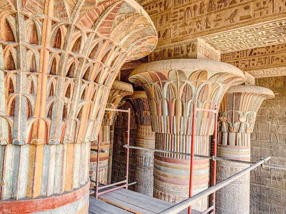
Most people know by now that ancient Egyptian, Greek, and Roman buildings were a riot of colour:

Egptian columns

Reconstruction of a polychrome Greek temple

As were Gothic cathedrals:

Gothic clustered columns

Even Victorian and Federation vernacular buildings, though their builders had only a limited range of relatively subdued natural (and a few synthetic) pigments to work with, seem positively joyous compared to our desaturated modern streetscapes (but good luck finding a house from those periods that hasn’t been ‘refreshed’ to look ‘contemporary’).

Period Federation colour scheme

Probably a big part of the motive here, for both developers and home owners, is the same as that behind the fact that the vast majority of vehicles are white, silver-grey, or black: the desire for ease of resale. Houses are now painted not to present the individuality and taste of their long-term owner to the street, but to be as bland and inoffensive as possible, with one eye to flipping them for a profit a few years down the track.

This is a great pity, especially in the emphatically not-grey country of Australia, where a short walk in the bush will provide you with endless colour ideas, and where you could spend an entire career working only with the palette found on a single parrot or eucalyptus tree.


IN DEFENSE OF (SOME) MODERNISM

As a proponent of traditional design and architecture, I sometimes find myself in the position of wanting to defend the work of certain ‘modernist’ architects against the more strident ‘traditionalists’ on twitter and elsewhere who are as reflexively dismissive of all ‘modernist’ architecture as architectural progressives are of traditional forms. This blanket dismissal suggests to me that these critics haven’t really understood that what makes a building ‘traditional’ in part or whole is the degree to which it displays the underlying principles that constitute the ‘traditional’ in design, and are instead relying on superficial attributes or associations, such as era or style, in passing judgement. I always emphasise that traditional design has nothing to do with historicism or classicism, and that it is perfectly possible to do traditional architecture that is neither.

Traditional architectural principles are broadly hierarchical, and died in stages: first to go was ornament, but lack of ornament isn’t necessarily fatal to a building. Most of the architects of the period of early or ‘high’ modernism, though their work may be shorn of ornament, nevertheless preserved many of the other, arguably more foundational, principles of traditional design that were progressively lost over the following decades: natural materials, a degree of fractal scaling, local symmetries, a careful sense of proportion, plumb walls, rectilinear windows, and so on. Were you to bring them back, most of these architects would be appalled by the sterile, anti-human, parametric horrors of the architect-priests of our own time.

The modern cult of individual creative genius may have been disastrous for architecture as a whole, but that doesn’t mean that such figures don’t exist. And these architects certainly had their failures- the problem with free-floating, intuitive inspiration, as opposed to vernacular or classical design anchored in the communal rules of tradition and so almost infinitely forgiving of mediocrity, is that if the muse deserts you you aren’t left with much. But the best of the work of the best is, to me at least, undeniably beautiful, and represents a self-conscious but successful high-architectural invocation of the spirit of vernacular architecture. You might even, with some justification, call it ‘traditional modernism.’

Alvar Aalto

Alvar Aalto

Alvar Aalto

Gunnar Asplund

Gunnar Asplund

Luis Barragan

Luis Barragan

Jorn Utzon

Jorn Utzon


DESIGN CONDESCENSION

From time to time I come across articles on interior design blogs or in other places where the writer traces the development of a particular aspect of architectural or interior design through its history. In these articles, there is often a faint undercurrent of condescension or superiority, as if to say, ‘haha look at those silly premoderns, luckily we moderns know better.’ This attitude is driven by an underlying assumption of inevitable and endless progress, be it social, material or technological, that confers redundancy on everything that came before the present.

A good example of this is kitchen design. The author will sketch out the history of kitchens, comparing the separated and poky little lean-to kitchens of the nineteenth century unfavourably to the modern ‘open plan’ that is ubiquitous today, and imply bafflement that anybody would have chosen to do it any way other than we do. As an aside, it is stating the obvious to point out that between the two ends of this kitchen design spectrum there are all kinds of in-between ‘semi-open’ design possibilities that allow the best of both worlds, but for whatever reason these possibilities are rarely explored; nor in any case are the eminently rational motives behind the design decisions buried in these old and ‘primitive’ kitchens.

Before electricity and even gas, all cooking was done with wood or coal, and the risk of fire was very real. By separating the kitchen off the back of the house, the risk of a kitchen fire taking out the entire house was reduced, particularly in the case of a brick house where the lean-to kitchen was effectively fire-separated from the main dwelling. Cooking fires also generate a lot of heat, which isn’t necessarily wanted in the rest of the house, especially in an Australian summer.

No electricity also means no mechanical extraction fans, so a separate kitchen was the only way of preventing smoke, soot, oil, cooking smells, and water vapour from permeating the walls and furnishings of living areas.

These are only some of the ‘technical’ reasons for kitchens being the way they were; there are also social factors that I won’t go into here. The point is that the design decisions of past buildings shouldn’t be dismissed as historical or superannuated, but rather taken seriously and even learnt from.

Design, like evolution, has no telos; design features, like the features of biological organisms, simply represent the fittest or best responses to the prevailing conditions of the environment in which they exist. If, as I believe, we are leaving our historically anomalous environment of extreme energy and resource abundance, and re-entering an environment of energy and resource scarcity that is almost beyond living memory in the first world, then we will also witness a reversal of the design ‘progress’ seen by techno-progressives as irreversible, and the re-emergence of many of the design elements, and much of the design wisdom, contained in old kitchens and other spaces.


JAPANESE MINKA VI - THREE ROOM LAYOUTS 2

Last week we examined the three room layouts that evolved within the tatebunwari pattern, where the basic principle of room division is that of transverse ‘columns’ across the dwelling - the room adjacent to the doma (typically called the hiroma) bounds the doma for its full width, and the rooms further ‘in’ are generally parallel to the hiroma and also span the full width of the dwelling. This week we will look at the other subgroup of three room layouts: those that developed from the yokobunwari pattern, where room divisions are longitudinal, and more than one room bounds the doma.

The first subtype of the yokobunwari pattern is called the mae-zashiki-gata 前座敷型or ‘front zashiki’ type. In the example of this type shown below, we have the front zashiki of the title, where more formal or public-facing activities would take place, and also possibly more utilitarian activities in the area of the zashiki bordering the doma. To the rear of the zashiki are two rooms: the doma-bordering daidoko 台所, where eating of meals and other household activities were undertaken. The daidoko might also be used for sleeping. At the most ‘interior’ part of the dwelling is the nema 寝間, used mainly for sleeping.

The maezashiki type, yokobunwari pattern.

The second type is called the tatenarabi sanma-dori 竪ならび三間取り which I will call the ‘row type’ in contrast to the ‘column type’ discussed in the last post. Here the three rooms are arranged parallel to one another so that each borders the doma on their short side. The example below is typical, with again the front zashiki, the middle daidoko, and the rear heya for sleeping.

Tatenarabi sanma-dori type of the yokobunwari pattern.

Analysing these patterns and layouts and contemplating the possibilities inherent to each pattern and type can be a productive exercise for any architect or designer. Without corridors or other distracting auxiliary spaces, they have the purity of architects’ schematic bubble diagrams, but made real; there is an appealing directness and clarity to the functional and spatial relationships they contain.


JAPANESE MINKA V - THREE ROOM LAYOUTS

Further to last week’s post on two room layouts and the two ways in which these rooms can be arranged - the tatebunwari and yokobunwari patterns - I would now like to examine the sub-variations that emerge from these two patterns when they are developed into three room layouts, beginning this week with tatebunwari layouts.

The tatebunwari pattern can be further broken down into two sub-types: the heiretsugata, or what I will call the ‘column type’ layout, and the hiromagata or ‘hiroma type’ layout.

In the heiretsugata type, the rooms are arranged in transverse ‘columns,’ with the ‘outermost’ room fully and exclusively bordering the doma. In the example shown below, this room is called the gozen, typically where meals, family ‘together time’ and handwork would take place; further in comes the omote, for sleeping and other activities, and then the innermost tsubone, for receiving guests and other more ceremonial or formal activities.

A typical tatebunwari pattern minka of the subtype heiretsugata or ‘column’ type.

In the hiromagata type, the ‘everyday’ space (in the example below called the hiroma) again fully borders the doma. Hiroma in general usage simply means a wide or large room; in the context of rural minka it is the ‘general’ room for eating and other everyday activities. The inner portion of the raised floor area is here divided not transversely but longitudinally, into the rear heya (literally ‘room’) for sleeping, and the front zashiki, a formal space for the entertaining of guests, etc.

A typical tatebunwari pattern minka of the subtype hiromagata or ‘hiroma type’.


JAPANESE MINKA IV - TWO ROOM LAYOUTS

In its simplest and probably most common form, the minka is rectilinear in plan, and so a useful way of thinking about the internal partitioning and functional organisation of the minka is in terms of two axes: the longitudinal and the transverse. The transverse axis might be thought of as the ‘front-back’ axis, with the front as the public side, the ‘face’ of the house, ideally the south or sun side, and the back the private, ‘dark’ side; the longitudinal axis might be thought of as the ‘in-out’ axis, with the doma at the public, ‘out’ end and the most private or formal areas at the ‘in’ end. This can be illustrated by the following example of the hito-ma or ‘single room’ minka discussed in last week’s post.

Two room minka are a natural evolution from the single room typology and represent a greater need for functional differentiation and/or a greater level of affluence. Two room minka were still typically found amongst the lower and poorer strata of society, however, and as such they were only required to fulfill the most essential functions of everyday life, with relatively little ‘specialisation’ of spaces, and little need for exclusively formal rooms for activities such as entertaining guests or conducting ceremonies.

The single room layout can be developed into a two room configuration in one of two ways, depending on which axis the ‘room’ in the above plan is divided. In the tatebunwari (竪分割) or ‘transverse partition’ type, the room is divided transversely, so that the doma and the two rooms are arranged in series along the ‘in-out’ axis. In the example shown below, the hiroma 広間 is roughly equivalent to a living room, an every day space for eating, handwork, etc. and also used for sleeping. The zashiki 座敷 is a more formal space than the hiroma, for the use of the master of the house and his guests.

A two room minka of the ‘vertical division’ type.

In the yokobunwari (横分割) or ‘longitudinal partition’ type, the room is divided longitudinally, so that the two rooms are on the ‘front-back’ axis, and each borders onto the doma. In the below example, the nema (寝間) is a sleeping space, but also used for other activities. The omote (表 or おもて) is the more formal ‘front room,’ but not typically as reserved in its use as the zashiki.

A two room minka of the ‘horizontal division’ type.


JAPANESE MINKA III - SINGLE ROOM LAYOUTS

After looking at the ancient antecedents of the minka in the previous two posts - the tateana pit dwelling and the takayuka raised floor dwelling - in this post we will examine the first step in the evolution of the minka proper- the combination of these two archetypes.

Note also that here we will be considering only the subcategory of minka known as nou-minka, the rural farmhouse, and not the better-known machiya, the urban townhouses so characteristic of cities like Kyoto.

To anyone with both romantic and ascetic inclinations, the purity of minka interiors is compelling. Without internal corridors and often without permanent internal partitions, even many ‘multiple room’ minka are still in a sense one-room dwellings, or at least ‘one space’ dwellings, united under a single ceilingless roof.

Interior view showing the roof structure of the Hakogi sennenya, the oldest extant minka in Japan, dated to the late Muromachi era (1336 - 1573)

The vast majority of minka consist of both a doma, the earthen-floored area which contains the dwelling entrance and is used for cooking and ‘utility’ work, and where footwear remains on; and the timber-framed raised floor takayuka, which is generally accessed by ‘going up’ via the doma after footwear is removed. Since the doma is universally present, it can be omitted in analyses of the interior layout, and any count of the number of rooms in the minka does not include the doma. So a ‘one-room’ minka contains two areas that are functionally differentiated, but in most cases not physically divided and so constituting a single space: the doma, which is not considered a ‘room’, and and the takayuka, which is.

As the humblest and simplest of minka, one-room layouts were found all over Japan, often for the use of religious or other ‘retirees.’ This single space happily accommodated all the activities of pre-modern daily life, and, as is the case with single-space dwellings of other cultures around the world, the apparent simplicity of the plan belies the unspoken but well-evolved and sometimes severe conventions that dictate the use of the space, conventions that display what you might call ‘folk rationality.’

In the example from Shiga Prefecture shown below, the doma (here called niwa) is used for cooking, indoor farm-work, and the storage of food and agricultural implements; the threshold area of the takayuka heya (literally ‘room’) adjacent to the niwa is used for taking meals and ‘handwork’; the narrow nure-en or ‘verandah’ along the facade is used for conversing with neighbours and as the entry point for guests, who were received in the area in front of the butsudan or Buddhist altar; the ‘back’ corner of the heya in front of the tokonoma or alcove was used for sleeping. In this informal division of the space by function, we can see the germ of later multi-room minka in which the single room has been partitioned off into three, but the functional relationships nevertheless remain intact.

A hito-ma or one room dwelling showing the functional division of the space.


JAPANESE MINKA II - THE RAISED-FLOOR DWELLING

As discussed briefly at the end of the last post, the tateana-juukyo pit dwellings of the Jomon period gradually gave way from around 2,300 years ago to a new building typology brought from the Asian mainland by the Yayoi people: the takayuka-shiki juukyo or ‘high/raised floor style dwelling’, often shortened to takayuka juukyo. Where the Jomon were hunter-gatherers, the Yayoi were rice agriculturalists; it is likely that the original impetus behind the development of raised-floor structures was the need to preserve the rice harvest from both damp and vermin, and that the earliest of these structures were grain stores rather than residential buildings. But it couldn’t have been long before people realised that the raised floor confers the same advantages to humans as it does to grain.

The typical takayuka juukyo consisted of four or more posts sunk deep into the ground, on top of which was built the elevated floor structure, walls of plank, reed, or clay, and a gable roof of log underpurlins and rafters, topped with thatch.

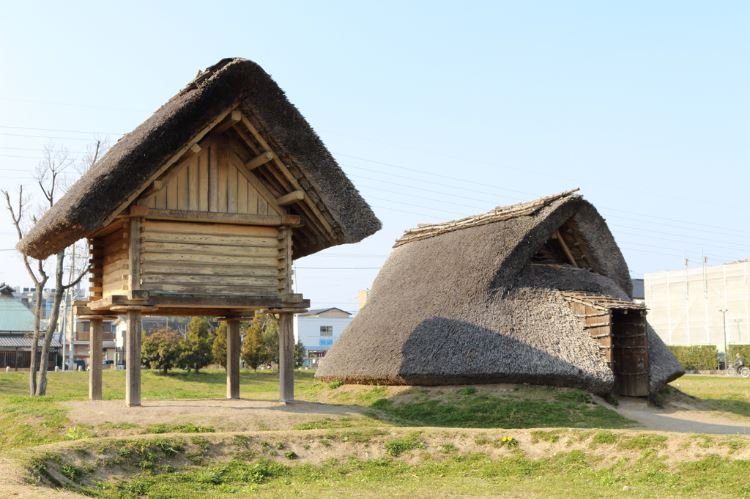
A raised-floor granary standing next to a pit dwelling, presumably a common sight (though probably with greater fire separation!) in the transitional period before pit dwellings gave way to raised floor dwellings. A much higher level of sophistication is evident in the raised floor structure, in both the structural system and in the dressing and joining of timbers. Note the disc-shaped caps on the posts to prevent rats and other vermin from entering.

A highly refined example of the raised floor typology, with finely worked timbers and close-fitting plank walls.

In the pit dwelling and the raised floor dwelling we have the two antecedents to, and near-universal elements of, Japanese residential architecture up to the present day. Until relatively recently, all Japanese houses consisted of a both a raised floor ‘interior’ of planks or tatami mats, where sleeping, relaxing, eating, receiving guests, praying and the like took place; and a doma: an earth-floored area where all the dirty ‘utility’ activity of the household, including cooking, happened.

An expansive earthen floored doma in a traditional farmhouse, with a raised floor of thick planks beyond.

Modern Japanese houses are almost all raised floor; there are few houses with significant doma and almost none of the ‘slab on grade’ floors that predominate in Australia, as the Japanese building code requires in principle that the finished floor level of habitable rooms be at least 450mm above ground level. The pit dwelling survives only atavistically as the genkan, the ‘sunken’ entrance area to the Japanese home, found even in the tiniest apartments, that functions as a transitional space between outside and the raised floor of the interior, where shoes are taken off before ‘going up’ into the house.

A tiny apartment genkan demonstrating one of its functions: stopping leaves and other debris from going further into the house.

This genkan in a traditional building, with granite paving stones set into a beaten-earth floor, is evocative of its Jomon ancestry.


JAPANESE MINKA I - INTRODUCTION AND PIT DWELLINGS

Feeling ambitious, I have decided to do a series of posts on minka, the traditional vernacular residential architecture of Japan. Minka (民家), literally ‘people’s house’ or ‘folk house,’ is the Japanese word for any ‘common’ or vernacular dwelling, traditional or contemporary, as opposed to both the refined and self-consciously ‘classical’ historical tradition, represented by the villas and tea houses of the aristocracy, residences attached to temples and shrines, and the like, and to modern ‘architectural’ design. In practice, minka is often used more narrowly to refer to traditional residential structures built until the middle of the 20th century.

My main reference in this series will be Kawashima Chūji’s comprehensive three-volume survey and study titled Horobiyuku Minka (滅びゆく民家) or ‘Disappearing Minka’. There is already an excellent English translation of this work, albeit abridged into one volume, by Lynne E. Riggs, but neither the original nor the translation are widely known or cheaply available. Totalling almost 900 pages and heavily illustrated with photographs, sketches, diagrams, plans and sections, the work and its subject certainly deserve a wider audience, so I hope to be able to present at least some of its contents here to anyone who is interested. The three volumes are subtitled: Roofs and Exteriors (YaneGaikan 屋根・外観); Internal Layouts, Structure, and Interiors (Madori・Kо̄zо̄・Naibu 間取り・構造・内部) ; and Sites/Auxiliary Structures and Typologies (Yashiki-mawari・Keishiki 屋敷まわり・形式) respectively. I will probably be focusing mostly on the second volume.

Before diving in, however, it would probably be a good idea to lay the groundwork by looking briefly at the archaeological and historical origins of the minka.

The history, or rather pre-history, of minka begins with tateana-shiki jūkyo (竪穴式住居) or simply tateana jūkyo 竪穴住居), the pit (tateana 竪穴) dwellings thought to have first appeared in the late palaeolithic, but more closely associated with the Jо̄mon period (roughly 14th to 1st millenium BC) and surviving into the subsequent Yayoi period (roughly 3rd century BC to 3rd century AD). These structures consist of a pit, round or later rectilinear, with the excavated material often used to form a low wall or berm around the perimeter. The depth of the pit floor to the top of the berm varied by period and region; in cold areas it could be two metres or more. Posts (typically four but sometimes two, three, five, or more) were set into the floor of the pit and tied together with beams, which supported a roof consisting of rafters running from ground to ridge, purlins, and a covering of earth/turf or later thatch.


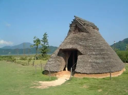
Modern reconstruction of a tateana-jūkyo (gable entry).


Modern reconstruction of a tateana-jūkyo (side entry).


Reconstruction of the interior of a tateana jūkyo


Cutaway showing the structure of a tateana jūkyo.


An excavated tateana jūkyo pit showing post holes and fireplace, the structural framework, and a reconstruction of the external appearance showing thatching, entrance opening, and smoke openings in the gables.


A series of sections showing the evolution of the tateana jūkyo roof structure, from a simple earth-covered A-frame to a thatched structure with differentiated wall and roof, essentially identical to a modern house but for the sunken floor.


Later, relatively sophisticated examples of the form, showing square plan, hipped-and-gabled roof, ‘chimneys’, and perimeter wall posts and beams which allow the roof structure to be raised clear of the ground.


The Japanese climate is classified as ‘temperate’ over most of its range, which might surprise anyone who has been there in August or February. Builders of houses in most parts of the archipelago have always been faced with the challenge of balancing the competing requirements of hot, humid summers and cold, humid winters, often with significant snowfall. The tateana jūkyo sucessfully addressed many of these challenges. The insulative thatch and the thermal mass of the earth surrounding the pit acted to keep the interior within a comfortable temperature range, around 23 degrees celsius in summer and 20 degrees in winter. The smoke holes in the gables provided effective cross ventilation and exhausted the bulk of the smoke from the fire; at the same time the permeable thatching, while preventing rain from entering the house, also allowed smoke to diffuse from the inside out, which both fumigated the thatch against insects and rodents and preserved it against rot.

Diagram showing the environmental performance of the tateana jūkyo.


Despite these advantages, the tateana jūkyo gradually gave way to the takayuka jūkyo (高床住居) or ‘raised floor’ dwelling, introduced to Japan by the Yayoi people in their migration from the continent beginning in the 3rd century BC, just as the rice agriculture of the Yayoi eventually displaced the hunter-gathering of the Jо̄mon. The takayuka jūkyo will be the subject of the next post.


CEILING HEIGHTS

If you’ve lived all your life in newer buildings, you’re probably familiar with the sense of expansiveness and ease you feel on entering a Victorian or Edwardian house, then noting how high the ceilings are compared to those in your own home. What happened?

Regulation of ceiling heights in Australia goes all the way back to 1810, when, under the Governorship of Lachlan Macquarie, an order was issued to the effect that “no Dwelling-house is to be less than nine Feet high” (this figure probably refers to the ‘pitching height’ of the rafters, which is de facto roughly the ceiling height). Presumably the order was felt necessary because builders and developers were trying to skimp on material costs by building low, and nine feet (2.7m) was settled on as the minimum required to provide amenity to occupants. In the Australian climate, tall rooms have the advantage of being cooler in summer, because warm air will pool near the ceiling, leaving cooler air near the inhabited zone at floor level- the difference can be 5° C or more. In the short mild winters, high ceilings presented less of a disadvantage than they do today, because heating then was radiant- open fireplaces heat surfaces and bodies directly, rather than heating the air of the entire space, as is the case with modern air conditioning systems. Taller rooms also allow for taller windows, allowing light to penetrate more deeply into rooms.

As the prosperity of the colonies grew, so did ceiling heights. In particular, a fall in material costs in the 1860s saw ceiling heights of twelve or even fourteen feet (3.6 or 4.2m) becoming relatively common in the homes of the affluent.

The 20th century saw ceiling heights swing back in the other direction. Following World War 2 in particular, austerity conditions and materials shortages put pressure on building regulations to reflect new economic realities, and the minimum ceiling height for habitable rooms was reduced from 9 to 8 feet (2.7 to 2.4m), where it remains today. This represents a reduction of just over 10% in required wall materials. Taller ceilings may also require taller cornices, skirting boards, doors and windows if they are to remain in proportion. Ceiling lights need to be more powerful or more numerous the further they are from the floor. In two storey houses, increasing the floor-to-floor height means more space and material required for the stairs. So dropping the ceiling can mean substantial savings, and for the ‘marginal’ prospective buyer whose ability to afford a house is borderline, the difference might mean being able to scrape together the deposit for a mortgage on an off-the-plan volume-built house.

While ceilings have dropped over time, the size of the average Australian house has more than doubled since 1950.  One way of interpreting this is that we've sacrificed vertical space for horizontal, and not because families have grown (they’ve shrunk), but to accommodate all our extra stuff. Vertical space is seen as not as useful for this purpose; its value is more intangible, more difficult to articulate, and harder to defend against the material advantages of ‘building out.’