JAPANESE MINKA III - SINGLE ROOM LAYOUTS

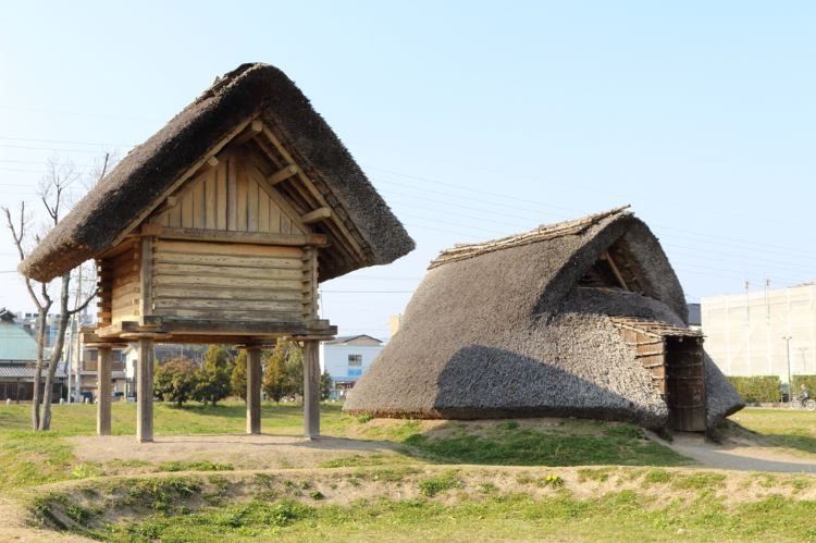
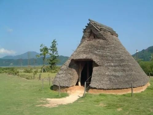
After looking at the ancient antecedents of the minka in the previous two posts - the tateana pit dwelling and the takayuka raised floor dwelling - in this post we will examine the first step in the evolution of the minka proper- the combination of these two archetypes.

Note also that here we will be considering only the subcategory of minka known as nou-minka, the rural farmhouse, and not the better-known machiya, the urban townhouses so characteristic of cities like Kyoto.

To anyone with both romantic and ascetic inclinations, the purity of minka interiors is compelling. Without internal corridors and often without permanent internal partitions, even many ‘multiple room’ minka are still in a sense one-room dwellings, or at least ‘one space’ dwellings, united under a single ceilingless roof.

Interior view showing the roof structure of the Hakogi sennenya, the oldest extant minka in Japan, dated to the late Muromachi era (1336 - 1573)

The vast majority of minka consist of both a doma, the earthen-floored area which contains the dwelling entrance and is used for cooking and ‘utility’ work, and where footwear remains on; and the timber-framed raised floor takayuka, which is generally accessed by ‘going up’ via the doma after footwear is removed. Since the doma is universally present, it can be omitted in analyses of the interior layout, and any count of the number of rooms in the minka does not include the doma. So a ‘one-room’ minka contains two areas that are functionally differentiated, but in most cases not physically divided and so constituting a single space: the doma, which is not considered a ‘room’, and and the takayuka, which is.

As the humblest and simplest of minka, one-room layouts were found all over Japan, often for the use of religious or other ‘retirees.’ This single space happily accommodated all the activities of pre-modern daily life, and, as is the case with single-space dwellings of other cultures around the world, the apparent simplicity of the plan belies the unspoken but well-evolved and sometimes severe conventions that dictate the use of the space, conventions that display what you might call ‘folk rationality.’

In the example from Shiga Prefecture shown below, the doma (here called niwa) is used for cooking, indoor farm-work, and the storage of food and agricultural implements; the threshold area of the takayuka heya (literally ‘room’) adjacent to the niwa is used for taking meals and ‘handwork’; the narrow nure-en or ‘verandah’ along the facade is used for conversing with neighbours and as the entry point for guests, who were received in the area in front of the butsudan or Buddhist altar; the ‘back’ corner of the heya in front of the tokonoma or alcove was used for sleeping. In this informal division of the space by function, we can see the germ of later multi-room minka in which the single room has been partitioned off into three, but the functional relationships nevertheless remain intact.

A hito-ma or one room dwelling showing the functional division of the space.


JAPANESE MINKA II - THE RAISED-FLOOR DWELLING

As discussed briefly at the end of the last post, the tateana-juukyo pit dwellings of the Jomon period gradually gave way from around 2,300 years ago to a new building typology brought from the Asian mainland by the Yayoi people: the takayuka-shiki juukyo or ‘high/raised floor style dwelling’, often shortened to takayuka juukyo. Where the Jomon were hunter-gatherers, the Yayoi were rice agriculturalists; it is likely that the original impetus behind the development of raised-floor structures was the need to preserve the rice harvest from both damp and vermin, and that the earliest of these structures were grain stores rather than residential buildings. But it couldn’t have been long before people realised that the raised floor confers the same advantages to humans as it does to grain.

The typical takayuka juukyo consisted of four or more posts sunk deep into the ground, on top of which was built the elevated floor structure, walls of plank, reed, or clay, and a gable roof of log underpurlins and rafters, topped with thatch.

A raised-floor granary standing next to a pit dwelling, presumably a common sight (though probably with greater fire separation!) in the transitional period before pit dwellings gave way to raised floor dwellings. A much higher level of sophistication is evident in the raised floor structure, in both the structural system and in the dressing and joining of timbers. Note the disc-shaped caps on the posts to prevent rats and other vermin from entering.

A highly refined example of the raised floor typology, with finely worked timbers and close-fitting plank walls.

In the pit dwelling and the raised floor dwelling we have the two antecedents to, and near-universal elements of, Japanese residential architecture up to the present day. Until relatively recently, all Japanese houses consisted of a both a raised floor ‘interior’ of planks or tatami mats, where sleeping, relaxing, eating, receiving guests, praying and the like took place; and a doma: an earth-floored area where all the dirty ‘utility’ activity of the household, including cooking, happened.

An expansive earthen floored doma in a traditional farmhouse, with a raised floor of thick planks beyond.

Modern Japanese houses are almost all raised floor; there are few houses with significant doma and almost none of the ‘slab on grade’ floors that predominate in Australia, as the Japanese building code requires in principle that the finished floor level of habitable rooms be at least 450mm above ground level. The pit dwelling survives only atavistically as the genkan, the ‘sunken’ entrance area to the Japanese home, found even in the tiniest apartments, that functions as a transitional space between outside and the raised floor of the interior, where shoes are taken off before ‘going up’ into the house.

A tiny apartment genkan demonstrating one of its functions: stopping leaves and other debris from going further into the house.

This genkan in a traditional building, with granite paving stones set into a beaten-earth floor, is evocative of its Jomon ancestry.


JAPANESE MINKA I - INTRODUCTION AND PIT DWELLINGS

Feeling ambitious, I have decided to do a series of posts on minka, the traditional vernacular residential architecture of Japan. Minka (民家), literally ‘people’s house’ or ‘folk house,’ is the Japanese word for any ‘common’ or vernacular dwelling, traditional or contemporary, as opposed to both the refined and self-consciously ‘classical’ historical tradition, represented by the villas and tea houses of the aristocracy, residences attached to temples and shrines, and the like, and to modern ‘architectural’ design. In practice, minka is often used more narrowly to refer to traditional residential structures built until the middle of the 20th century.

My main reference in this series will be Kawashima Chūji’s comprehensive three-volume survey and study titled Horobiyuku Minka (滅びゆく民家) or ‘Disappearing Minka’. There is already an excellent English translation of this work, albeit abridged into one volume, by Lynne E. Riggs, but neither the original nor the translation are widely known or cheaply available. Totalling almost 900 pages and heavily illustrated with photographs, sketches, diagrams, plans and sections, the work and its subject certainly deserve a wider audience, so I hope to be able to present at least some of its contents here to anyone who is interested. The three volumes are subtitled: Roofs and Exteriors (YaneGaikan 屋根・外観); Internal Layouts, Structure, and Interiors (Madori・Kо̄zо̄・Naibu 間取り・構造・内部) ; and Sites/Auxiliary Structures and Typologies (Yashiki-mawari・Keishiki 屋敷まわり・形式) respectively. I will probably be focusing mostly on the second volume.

Before diving in, however, it would probably be a good idea to lay the groundwork by looking briefly at the archaeological and historical origins of the minka.

The history, or rather pre-history, of minka begins with tateana-shiki jūkyo (竪穴式住居) or simply tateana jūkyo 竪穴住居), the pit (tateana 竪穴) dwellings thought to have first appeared in the late palaeolithic, but more closely associated with the Jо̄mon period (roughly 14th to 1st millenium BC) and surviving into the subsequent Yayoi period (roughly 3rd century BC to 3rd century AD). These structures consist of a pit, round or later rectilinear, with the excavated material often used to form a low wall or berm around the perimeter. The depth of the pit floor to the top of the berm varied by period and region; in cold areas it could be two metres or more. Posts (typically four but sometimes two, three, five, or more) were set into the floor of the pit and tied together with beams, which supported a roof consisting of rafters running from ground to ridge, purlins, and a covering of earth/turf or later thatch.


Modern reconstruction of a tateana-jūkyo (gable entry).


Modern reconstruction of a tateana-jūkyo (side entry).


Reconstruction of the interior of a tateana jūkyo


Cutaway showing the structure of a tateana jūkyo.


An excavated tateana jūkyo pit showing post holes and fireplace, the structural framework, and a reconstruction of the external appearance showing thatching, entrance opening, and smoke openings in the gables.


A series of sections showing the evolution of the tateana jūkyo roof structure, from a simple earth-covered A-frame to a thatched structure with differentiated wall and roof, essentially identical to a modern house but for the sunken floor.


Later, relatively sophisticated examples of the form, showing square plan, hipped-and-gabled roof, ‘chimneys’, and perimeter wall posts and beams which allow the roof structure to be raised clear of the ground.


The Japanese climate is classified as ‘temperate’ over most of its range, which might surprise anyone who has been there in August or February. Builders of houses in most parts of the archipelago have always been faced with the challenge of balancing the competing requirements of hot, humid summers and cold, humid winters, often with significant snowfall. The tateana jūkyo sucessfully addressed many of these challenges. The insulative thatch and the thermal mass of the earth surrounding the pit acted to keep the interior within a comfortable temperature range, around 23 degrees celsius in summer and 20 degrees in winter. The smoke holes in the gables provided effective cross ventilation and exhausted the bulk of the smoke from the fire; at the same time the permeable thatching, while preventing rain from entering the house, also allowed smoke to diffuse from the inside out, which both fumigated the thatch against insects and rodents and preserved it against rot.

Diagram showing the environmental performance of the tateana jūkyo.


Despite these advantages, the tateana jūkyo gradually gave way to the takayuka jūkyo (高床住居) or ‘raised floor’ dwelling, introduced to Japan by the Yayoi people in their migration from the continent beginning in the 3rd century BC, just as the rice agriculture of the Yayoi eventually displaced the hunter-gathering of the Jо̄mon. The takayuka jūkyo will be the subject of the next post.


CEILING HEIGHTS

If you’ve lived all your life in newer buildings, you’re probably familiar with the sense of expansiveness and ease you feel on entering a Victorian or Edwardian house, then noting how high the ceilings are compared to those in your own home. What happened?

Regulation of ceiling heights in Australia goes all the way back to 1810, when, under the Governorship of Lachlan Macquarie, an order was issued to the effect that “no Dwelling-house is to be less than nine Feet high” (this figure probably refers to the ‘pitching height’ of the rafters, which is de facto roughly the ceiling height). Presumably the order was felt necessary because builders and developers were trying to skimp on material costs by building low, and nine feet (2.7m) was settled on as the minimum required to provide amenity to occupants. In the Australian climate, tall rooms have the advantage of being cooler in summer, because warm air will pool near the ceiling, leaving cooler air near the inhabited zone at floor level- the difference can be 5° C or more. In the short mild winters, high ceilings presented less of a disadvantage than they do today, because heating then was radiant- open fireplaces heat surfaces and bodies directly, rather than heating the air of the entire space, as is the case with modern air conditioning systems. Taller rooms also allow for taller windows, allowing light to penetrate more deeply into rooms.

As the prosperity of the colonies grew, so did ceiling heights. In particular, a fall in material costs in the 1860s saw ceiling heights of twelve or even fourteen feet (3.6 or 4.2m) becoming relatively common in the homes of the affluent.

The 20th century saw ceiling heights swing back in the other direction. Following World War 2 in particular, austerity conditions and materials shortages put pressure on building regulations to reflect new economic realities, and the minimum ceiling height for habitable rooms was reduced from 9 to 8 feet (2.7 to 2.4m), where it remains today. This represents a reduction of just over 10% in required wall materials. Taller ceilings may also require taller cornices, skirting boards, doors and windows if they are to remain in proportion. Ceiling lights need to be more powerful or more numerous the further they are from the floor. In two storey houses, increasing the floor-to-floor height means more space and material required for the stairs. So dropping the ceiling can mean substantial savings, and for the ‘marginal’ prospective buyer whose ability to afford a house is borderline, the difference might mean being able to scrape together the deposit for a mortgage on an off-the-plan volume-built house.

While ceilings have dropped over time, the size of the average Australian house has more than doubled since 1950.  One way of interpreting this is that we've sacrificed vertical space for horizontal, and not because families have grown (they’ve shrunk), but to accommodate all our extra stuff. Vertical space is seen as not as useful for this purpose; its value is more intangible, more difficult to articulate, and harder to defend against the material advantages of ‘building out.’


A MIX OF COMPATIBLE MATERIALS

Over recent years, the idea has taken hold among architects and planning authorities alike that building facades need to display ‘modulation,’ ‘articulation,’ and ‘a variety of materials and colours’. The state of New South Wales seems particularly intrusive in this, going so far as to promote and even mandate these notions in its planning schemes. The Hornsby Development Control Plan 2013, for example, contains the following provisions for the street facades of medium density housing developments (basically townhouses and the like):

  • Articulation should be achieved by dividing all facades into vertical panels. Wall planes should not exceed 6 metres in length without an offset of at least 1 metre and a corresponding change in roof form.

  • Buildings should include structural elements such as sunshades, balconies and verandahs that provide variety in the built form.

  • Facades should incorporate a mix of compatible materials such as face or rendered brickwork and contrasting areas of light weight cladding.

  • Sunscreens and awnings comprised of timber battens or metal frames are encouraged.

It seems that what is being attempted, albeit in a crude and inchoate way, is the reintroduction of some degree of fractal scaling into the streetscape, although it is highly unlikely that the authors of the planning scheme would have described it in these terms. Rather, town planners probably perceived a need to respond to a creeping featurelessness or blandness of the modern developer-driven ‘builder’s vernacular’ without at the same time going to the other extreme of giving free reign to local architects with pretensions of ‘genius’ along the lines of a Gehry or Hadid. The problem they are faced with, probably insurmountable, is how to reconcile these two aims - the avoidance of ‘monotony’ on the one hand, and the imposition of ‘order’ on the other - within the framework of a modern architectural orthodoxy that regards them as contradictory and antithetical.

Traditional design, which is essentially self-regulating, had solved the uniformity/monotony - variety/chaos problem before it even arose. Traditionally, streetscapes displayed a stylistic and material uniformity and harmony within each building, and a degree of variety across different buildings, but each still bound by the constraints of traditional design and materials; today, on the other hand, we have chaotic variety within each building, and a kind of monotonous but equally chaotic sameness across buildings.

The traditional architect had no problem with a long, ‘flat’ facade plane completely lacking in ‘offsets,’ because he knew he could easily avoid a monotonous or oppressive appearance by effectively articulating it on both a wider and a finer range of scales than is typically seen today - that is, by the use of pilasters, string courses, cornices, window sashes with small panes set in muntins and deep window reveals in thick walls, a variety of brick bonds, material textures, and so on. Steps in and out in the facade are typically on the order of centimetres, not metres. Today we start with a flat facade, consisting of flat window frames set close to flush in a flat wall surface made up of flat panels of flat industrial metal and flat industrial brick, and grossly overcompensate by insisting that this facade be arbitrarily stepped in and out by metres, and that materials, colours, roof pitches, etc. be varied equally arbitrarily and randomly, with the aim of somehow providing ‘interest’. Predictably, the result this is that every duplex or townhouse development is essentially indistinguishable from any other: dutiful use of ‘a variety of materials and colours,’ thick square or three-sided ‘picture frames’ of alucobond or fibre cement around balcony openings and garage doors, upper levels cantilevered out over brick lower levels, glass balustrades, and random skillions.

A particular modern favourite is to use two or more different brick colours in large ‘panels’ in a facade. Look at any old brick building, in contrast, and you will rarely find more than one brick colour used; where you do, there is a clear dominant or ‘ground’ brick colour, and the other is the ‘figure’ employed to pick out highlights at corners, around windows, and so on. The variety is in the service of expressing a structural or functional differentiation. It was understood that buildings need to project a sense of visual unity.

19th century townhouses in Millers Point, Sydney. With no variety of materials or offsets in the facade plane, presumably this ‘design’ would not be permitted today.

Hotel in The Rocks, Sydney. The facade displays fine-grained ‘offsets’, ornament, and a subtle variety of colours and finishes, differentiated rationally and functionally.


TRADITIONAL DESIGN II: UNIVERSAL DISTRIBUTION

This is the second in a series of posts exploring the ideas of the mathematician and design theorist Nikos Salingaros, and by extension his collaborator, the architect Christopher Alexander.

The previous post in this series examined the idea of a universal scaling hierarchy and how it could assist designers in deciding how many scales should be employed in buildings, and what the ratios between them should be.  This post and the next will consider the concept of universal distribution, as a way of answering another important question: how ‘full' should each scale be? or how many elements should each scale in the hierarchy contain? 

Imagine you set out to design a tree. While universal scaling is concerned with how big the 1st order branches should be in relation to the trunk, how big the 2nd order branches should be in relation to the 1st order branches, and so on, universal distribution is concerned with how many branches should be on the tree, and how many twigs, and how many leaves.

A good place to begin exploring universal distribution is by looking at the structure of fractals.  For our purposes, a fractal is any pattern that is generated recursively, and has the property of scaling symmetry: it is self-similar at various scales, meaning that you can zoom in on any part of the pattern and it will look identical or near-identical to any other level of magnification, and will contain the same amount of detail.  Fractals also have the interesting property of fractal dimensionality, but this property is less relevant to our purposes. 

One of the simplest fractals is the Koch snowflake.  Starting with an equilateral triangle, add to it three triangles with sides 1/3 the length of the original (meaning the scaling factor is 3); to the sides of these triangles add nine triangles with sides 1/3 their length; and so on.

The Koch snowflake

The Koch snowflake


Another simple triangle-based fractal is the Sierpinski gasket. In a sense it is the inverse of the Koch snowflake: it is subtractive (‘perforated') where the snowflake is additive (‘accretive'), and' ‘ingrown' where the snowflake is ‘outgrown.'  Also, the scaling factor here is 2, not 3.  Neither of these factors are very close to 2.72, which was proposed in the last post as a good approximation of the universal scaling hierarchy, but this doesn’t matter here: we are using fractals not to prove a point about universal scaling (we could easily create a fractal with a scaling factor of 2.72 if we wanted), but to introduce the concept of universal distribution.

 
The Sierpinski gasket

The Sierpinski gasket


The distribution of elements in the Sierpinski gasket is as follows:

0th order scale:  1 element

1st order scale: 3 elements

2nd order scale: 9 elements

3rd order scale: 27 elements

4th order scale: 81 elements

The distribution factor in this case is 3, i.e. each scale contains three times the number of elements of the previous scale.

As with the Fibonacci sequence (also recursive), fractals are everywhere in nature: trees and river systems are familiar examples.  People find these recursive, scale-symmetrical structures inherently pleasing, because they generate just the right amount of information compression in the brain: they are neither monotonous, like a grid of triangles all of the same size, nor chaotic, like a field of triangles of random size, position, and rotation.  The former possesses the necessary quality of order, but has no sense of life; it doesn't contain enough complexity to hold the mind's attention.  The latter produces a sense of anxiety, because the mind cannot derive any rules or patterns from it to reduce the computational load.  The objects and environments that give us the greatest satisfaction occupy a ‘Goldilocks zone' between these two extremes.  They exhibit scaling coherence: they have structures at different scales, a scaling hierarchy, and a high degree of self-similarity at different ‘magnifications.' Neither simplistic nor chaotic, they stimulate the mind without overwhelming it.

How does this apply to buildings?  Consider the baroque facade of Santa Maria in Vallicella, Rome.

Santa Maria in Vallicella, Rome

Santa Maria in Vallicella, Rome

There are bare areas devoid of detail, and within these areas there are centres of focus where the detail is concentrated, particularly around the parts of the facade where one's attention is naturally directed, such as doors and windows (incidentally, but not coincidentally, the human face displays the same kind of detail distribution: bare areas such as the cheeks and forehead, and smaller areas of concentrated, expressive detail, such as the mouth and eyes).

The facade of the gothic/romanesque Siena Cathedral shows a much denser distribution of detail typical of much gothic architecture - its distribution factor is higher than that of Santa Maria in Vallicella - but even here there is a hierarchical arrangement of blank areas and areas of greater detail.

Siena Cathedral

Siena Cathedral

Now let’s look at some pathological examples of universal distribution, or rather its lack.  Take a textbook example of ‘high modernism,' the Villa Savoye by Le Corbusier.

Villa Savoye

Villa Savoye

The facade contains only a few large scales; it is almost completely devoid of small-scale details, and the mid-range scales are absent.  The result is flat, barren, and unnatural; the building lacks the characteristics of universal scaling and distribution found in nature.

The lifeless character of ‘white box modernism’ was recognised as a problem, at least implicitly, by the post-modernists and deconstructivists, but in rejecting high modernism without understanding the root cause of its shortcomings, they only fell into another set of problems.  The facades below are representative. They contain only one scale, or perhaps not even that. Are they all detail, or all blank?  There is no hierarchy, only monotony.  In the end, the effect is every bit as dead as the modernist deadness these contemporary architects were presumably seeking to avoid.

thebarcodeproject.jpg
timber facade.jpg
officeelf.jpg


21 DESIGN RULES FROM 1855

The following is taken from The Register of Rural Affairs, published in America in 1855.  I think it holds up pretty well :)

1.  Always compare the cost with the means, before deciding on the plan.  It is much better to build within means, than to have a large, fine house, hard to keep in order, and encumbering the owner with a heavy and annoying debt.  A great error with many is an attempt to build finely.  Attend to real wants and substantial conveniences, and avoid imaginary and manufactured desires.

2.  Study a convenient location rather than a showy one: a house on a lofty hill may make a fine appearance, but the annoyance of ascending to it will become greater on each successive day.

3. Build of such good materials as are near at hand.  An interesting index is thus afforded to the resources and materials of that particular region, with the addition of great economy over the use of such as are “far brought and dear bought."

4. Prefer lasting to perishable materials, even if more costly.  A small well built erection, is better than a large decaying shell.

5. Discard all gingerbread work, and adopt a plain, neat, and tasteful appearance in every part.  Far more true taste is evinced by proper forms and just proportions than by any amount of tinsel and peacock decorations.  A marble statue bedizened with feathers and ribbons, would not be a very pleasing object.

6. Proportion may be shown in the smallest cottage as well as in the most magnificent palace - and the former should be carefully designed as well as the latter.  However small a building may be, let it never show an awkward conception, when a good form is more easily made than a bad one. 

7. Where convenient or practicable, let the plan be so devised that additions may be subsequently made, without distorting the whole.

8. More attention should be given to the convenient arrangement and disposition of rooms in constant daily use, that those employed but a few times in the course of a year.  Hence the kitchen and living-room should receive special attention.

9. In all country houses, from the cottage to the palace, let the kitchen (the most important apartment,) always be on a level with the main floor.  It requires more force to raise a hundred pounds ten feet upwards, whether it be the human frame or an assortment of eatables, than the same weight one hundred feet on a level.  To do it fifty times a day is a serious task.  If the mistress superintends her own kitchen, it should be of easy access.  For strong light and free ventilation, it should have, if possible, windows on opposite or nearly opposite sides.

10. There should be a set of easy stairs from the kitchen to the cellar.  Every cellar should have, besides the stairs within, an outside entrance, for the passage of barrels and other heavy articles.

11. The pantry, and more especially the china closet, should be between the kitchen and dining room for easy access from both.

12. The bathroom should be between the kitchen and nursery, for convenience to warm water.

13. Let the entry or hall be near the center of the house, so that ready and convenient access may be had from it to the different rooms; and to prevent the too common evil of passing through one room to enter another.

14. Place the stairs so that the landing shall be as near the center as may be practicable, for the reasons given in the preceding rule.

15. Every entrance from without, except to the kitchen, should open into some entry, lobby, or hall, to prevent the direct ingress of cold air into rooms, and to secure sufficient privacy.

16. Let the partitions of the second floor stand over those of the lower, as nearly as possible, to secure firmness and stability.

17. The first floor of any house, however small, should be at least one foot above ground, to guard against dampness.

18. Flat roofs should be adopted only with metallic covering.  Shingles need a steeper inclination to prevent the accumulation of snow, leakage and decay - more so than is frequently adopted.  A steep roof is, additionally, cheaper, by admitting the use of a less perfect material for an equally perfect roof, and giving more garret room.

19. The coolest rooms in summer, and the warmest in winter, are those remote from the direction of the prevailing winds and from the afternoon sun.  Hence parlors, nurseries, and other apartments where personal comfort is important, should be placed on this side of the house where practicable.

20. Always reserve ten per cent. of cost for improvement and planting.  Remember that a hundred dollars in trees and shrubbery produce a greater ornamental and pleasing effect than a thousand in architecture.

21. Lastly, never build in a hurry; mature plans thoroughly; procure the best materials, and have joiner-work done at the cheaper season of winter, and the erection will be completed in the most perfect manner, and with the greatest practicable degree of economy.


TRADITIONAL DESIGN I: UNIVERSAL SCALING

This is the first in a series of posts exploring the ideas of the mathematician and design theorist Nikos Salingaros, and by extension those of his mentor and collaborator, the architect Christopher Alexander.

introduction

Buildings, like biological organisms, are organized at a number of different scales, from the largest (the overall dimensions of the building) to the smallest (the texture of the sand in a render coat). This fact presents the architect or designer with a choice: he may either explicitly address it, and attempt to answer the questions and challenges it raises in the design process; or he may choose to ignore it and evade its challenges entirely; either way, his choice will be evident in the results.

How many scales should a building contain? What should the ratios between them be? How many elements should each scale contain? And what should the ratios between the number of elements in each scale be? All of these questions point to a deeper issue: why are some buildings so beautiful and seem so healthy, while others are so ugly and pathological?

This and subsequent posts will try to answer the above questions via an exploration of the ideas of Nikos Salingaros, with the aim of outlining a simple and practical methodology that can might be useful to anyone whose interest is in designing buildings that are beautiful and healthy, rather than ugly and sick.

the universal scaling sequence

You are probably familiar with the Fibonacci sequence, where each number in the series is the sum of the previous two numbers, beginning with 0 and 1:

0, 1, 1, 2, 3, 5, 8, 13, 21, 34, 55, 89, 144, 233, 377 . . .

From this we can derive another sequence, more relevant to our purposes, called the universal scaling sequence, which is obtained by removing alternate terms from the Fibonacci sequence:

1, 3, 8, 21, 55, 144, 377 . . .

The universal scaling sequence can be applied to architectural design in the following way: assign the arbitrary size of 1 to the largest scale in a building, then to the next scale down in size (in the same linear dimension) assign the value 1/3, then 1/8, then 1/21, and so on.  Or, start at the other end and assign to the smallest scale in a building the arbitrary size of 1, then the next scale up in size should be 3, then 8, then 21, and so on. 

To see how this works, try the following: start with a blank building facade with an overall height of 10m, which is your ‘first-order’ or ‘1’ scale.  From this, the sequence might suggest a floor-to-floor height of 10m/3 = 3.33m, a window height of 10m/8 = 1.25m, an ornamental cornice height of 10m/21 = 475mm, a sill or window frame height of 10m/55 = 180mm, and finer ornamental details at 10m/144 = 70mm and 10m/377 = 25mm.  Now do the same for the horizontal dimensions.  Say the facade is 6m wide: 6m/3 = 2m, 6m/8 = 750mm, 6m/21 = 285mm, 6m/55 = 110mm, and 6m/144 = 40mm.  Using these figures, I drew the facade below in about 15 minutes, letting the scales determine the design without much input from my ‘individual creativity.’

test Model (1).jpg

It’s nothing special, but that’s the point- designing in this way is highly forgiving.

Interestingly, if you take any term from the Fibonacci sequence and divide it by the previous term (e.g. 233/144), the number obtained approaches the famous golden mean, 1.618, as the two terms get larger.  Likewise, if you divide any term from the universal scaling sequence by the previous term, the answer approaches 2.618, which is the square of 1.618. However, because the Fibonacci sequence is not a true geometric sequence (where each term is the nth power of the previous term), it is impractical to use it in most design situations.  Nikos Salingaros proposes the natural logarithm e, 2.718, as an acceptable geometric substitute.

 
The Fibonacci sequence in nature

The Fibonacci sequence in nature

A logarithmic spiral in nature

A logarithmic spiral in nature

These constants are not just arbitrary abstractions: they are found throughout the natural world (hence the name universal), from spiral galaxies to molluscs to the number of petals on flowers.  Their great aesthetic and mathematical appeal sometimes tempts architects into designing golden rectangles into their buildings, citing the (possibly apocryphal) example of the Parthenon, or designing buildings that look like seashells and other organic forms.  These kinds of applications are over-literal and fundamentally misconstrued.  The real significance of the universal scaling sequence is that it provides a useful tool for checking that a building's various scales (the dimensions of building elements as measured along the same axis) are a reasonable approximation to the ‘natural' hierarchy of the universal scaling sequence, i.e.:

1. Few scales of the sequence are missing;

2. There are no significant scales that fall between the terms of the sequence; and

3. The ratios of adjoining scales are close enough to 2.618, or 2.718. 

Of course, real-world considerations mean that the scales in actual buildings will rarely conform to the mathematical ideal. In practice, the ratios are rounded off into rules of thumb, like the vernacular builder's ‘rule of three’: each scale in a building should be roughly three times the size of the next smallest scale, and 1/3 the size of the next largest.  At any rate, the important thing is not strict adherence to the numbers, but understanding the concept of the universal scaling hierarchy as an ideal to aim for.

Adoption of the universal scaling hierarchy has several benefits: it imposes non-arbitrary limitations on design (limitations are good); it guides the designer in making more effective design decisions; and it aids in the diagnosis of design flaws.  If a building or facade feels too busy, for example, it may be because it contains too many scales that fall between those on the universal scaling sequence.  Conversely, omitting scales from the sequence results in a collapse of the scaling hierarchy and a barren, lifeless appearance. 


Inappropriate spacing of scales and collapse of the hierarchy: only a few large and seemingly random scales are present in this facade.

Inappropriate spacing of scales and collapse of the hierarchy: only a few large and seemingly random scales are present in this facade.

This classical facade presents a full hierarchy of scales, from large (the distance between columns) to small (the width of the dentils in the cornice).

This classical facade presents a full hierarchy of scales, from large (the ‘bay’ or distance between columns) to small (the width of the dentils in the cornice).

Consider another example: a door and its architrave.  If the door is a standard 820mm wide door, universal scaling would suggest an architrave with a width of 820 / 2.718 = 300mm or so.  This might sound excessive, but if the architrave itself is further subdivided (by mouldings, painted or carved patterns, or other ornament) into successively smaller scales in the hierarchy (say 110mm, 40mm, and 15mm), the result is a door with great presence.  Economic realities generally meant that such opulent doors were reserved for classical or civic architecture; in humbler vernacular buildings, architraves were typically around 100mm wide, which skips a scale but is still far more effective in expressing the idea of ‘doorness’ than a modern ‘architectural’ door, which might have an ‘architrave’ as thin as 10mm.  In this case there are three scales missing between the scale of the door width and the scale of the frame width, which is a bit like a tree consisting of a single, massive trunk covered in tiny twigs: our brains cannot ‘span the gap' between the two scales to form a coherent connection between them, and the hierarchy collapses. 


Classical door with ornamented surround

Classical door with ornamented surround

Modern door with "frame"

Modern door with "frame"

Given that the human perceptual system evolved in the natural world, where these scaling sequences and ratios are the literal rule, it should not be controversial to suggest that people have an instinctive affinity for correct scaling ratios, and that buildings designed around a universal scaling hierarchy hold an innate aesthetic and emotional appeal for us, as evidenced by the fact that such buildings are found across all ages and cultures, in both classical architecture and vernacular building traditions.  In fact, as Salingaros points out, there are only two significant exceptions to this universality: one being the ‘death architecture’ of Egyptian Pyramids and defensive fortifications, both of which are deliberately designed to be repellent; and the other being modern architecture.


SKILLION ROOFS

A skillion roof or sometimes shed roof is a single-pitch or mono-pitch roof, in contrast to the traditional dual pitch gabled roof, where the two ‘pitches’ slope down symetrically from a central ridge to the longer walls of the building, producing the triangular gables on the shorter walls.

A skillion roof (a) and gable roof (b)

The skillion roof is generally defined as having a pitch (or gradient or fall) of at least 3 degrees or so; roofs shallower than that are usually referred to as flat roofs.

The use of skillion roofs in residential buildings seems to have originated in Australia, with architects such as Robin Boyd employing them as early as the 1950s, but the skillion roof remained largely confined to ‘magazine architecture’ for many years.

Date House by Robin Boyd, 1955

Much of its present popularity, and many of the ‘architectural’ examples of the form from the 1990s on, can be traced to the influence of a single figure: Australia’s defacto architect laureate, Glenn Murcutt, though his influence seems rarely acknowledged (Nemo propheta in patria?)

Murcutt’s skillion roofs are typically clad in corrugated iron, with unlined eaves supported on tapered steel or timber rafters and purlins and sometimes struts, a clerestory of sashless glazing running around the perimeter, and a clear datum separating the clerestory from the walls or glazing below.  The roof runs up to the north (southern hemisphere), the ceiling follows, and the depth of the eaves overhang on that side is carefully designed to exclude summer sun but allow deep penetration of winter light. Shading of the glazing below the datum is accomplished with external adjustable louvres.

Simpson-Lee House by Glenn Murcutt, 1993

But where Murcutt’s skillion roofs - influenced by his love of high modernism, fastidiously detailed, and genuinely functional - bought the form to a higher degree of refinement than earlier examples, the skillion’s later diffusion, first across the architectural world and then ‘down’ into the ‘builder’s vernacular’ to the point that it is now an established element and a common sight in volume-built subdivisions (though it has never come close to supplanting the gabled or hipped roof in popularity), has seen it often reduced to the status of empty stylistic gesture, a lazy, shorthand way of bringing together those shadowy twin concepts of contemporary and sustainable.

Examples at the ‘architectural’ end of the spectrum are often shamelessly plagiarised from Murcutt, but rarely executed with either his aesthetic subtlety or his fine-boned structural clarity. 

This is a winery, not a house, but a good example of what can happen when all you have is “ecologically sustainable outcomes”.

The ‘builder’s vernacular’ skillion has boxed eaves and fascia boards right around the roof: a stumpy, graceless profile.  It may be oriented any which way, and eaves depth is often arbitrary or insufficient.  There might be two or more skillions pitched in different directions on the same building.  There may be no clerestory and the ceiling underneath may be flat.  The skillion here is purely in the service of fashion or style, not function. 

A good example of the dog’s breakfast that is the skillion roof in the ‘builder’s vernacular’.

Though a well-designed and detailed skillion roof can be an effective solution to various environmental or other design considerations, one might still object to the form on a deeper level - call it psychological, or aesthetic, depending on your preference. That is, where the ceiling follows the pitch of the roof, the enclosed space, though dynamic in its asymmetrical upwards ‘loft’, lacks the stillness and serenity desired in a residential space.  The space of the room ‘drains out’ through the clerestory, as opposed to the way it ‘pools’ in the cathedral ceiling, with its obvious metaphors of the inverted hull or cupped hands, or in the flat ceiling, which forms a kind of shoebox lid on the room.  There is something settling about the traditional dual-pitch, symmetrical roof, with each side coming down from a central ridge to ‘cap’ the walls beneath, and in many cases eaves that project out over the walls, protecting them from weather, and if visible from within, serving as a comforting ‘cap-brim’ to the view. 


STEEP AND LOW ROOFS

One of the most characteristic elements of the 19th century Australian worker’s cottage is its roof. Steeply pitched with short spans and therefore low and compact in form, it is perfectly in keeping with the modest volumes it shelters. There are two basic types: either a parallel series of hipped or gabled units, themselves parallel to the street and separated by box gutters; or a U-shaped hipped roof, whose form is not immediately apparent when viewed from the front and sides, but becomes clear when viewed from the back: a box gutter, perpendicular to the street, runs down the middle of the house, separating the two hipped (or occasionally gabled) roofs that form the uprights of the ‘U’.

One explanation given for the emergence of these forms is that the unsophisticated colonial builders had a poor understanding of structural principles: the ceiling joists weren’t tied to the rafters to form a primitive triangulated truss and prevent the rafters from spreading the walls, and so the thrust exerted on the walls by the roof could only be controlled by keeping the span of the roof, and thus its mass, to a minimum. Low roofs with simple rise:run ratios such as 1:1 (45 degrees) or 1:1.3 (a 3-4-5 triangle, 37 degrees) were also easier to construct and required only short rafters.

Aside from these practical and material factors, early builders also no doubt had their aesthetic motivations, and understood very well that low, steep roofs suit these humble cottages perfectly and give them their unique appeal.

On the left: parallel gable roofs separated by a box gutter. On the right: a hipped ‘U’ form roof with an extremely long central box gutter (hidden).

On the left: parallel gable roofs separated by a box gutter. On the right: a hipped ‘U’ form roof with an extremely long central box gutter (hidden).

On the left: a ‘U’ form roof with a lean-to off the back. On the right: a parallel series of three hipped roofs separated by box gutters.

On the left: a ‘U’ form roof with a lean-to off the back. On the right: a parallel series of three hipped roofs separated by box gutters.

A ‘U’ form roof shown from the back, with twin hipped roofs separated by a box gutter

A ‘U’ form roof shown from the back, with twin hipped roofs separated by a box gutter


MOULDINGS VIII - THE CYMA RECTA AND THE CYMA REVERSA

In contrast to the simple mouldings covered in previous posts, in which each moulding consists of a single curve, the cyma recta and cyma reversa are examples of compound mouldings: mouldings that consist of two or more curves. In the case of the cyma (from the Greek for ‘wave’) mouldings, there are two curves in each, an ovolo and a cavetto, arranged in series.

The cyma recta consists of an ovolo at the bottom and a cavetto at the top:

In the cyma reversa, the order is reversed, with the cavetto at the bottom and the ovolo at the top:

The cyma recta and cyma reversa are examples of the general group of compound curves known as ogees (pronounced with a soft g), defined as double curves or arcs, one concave and the other convex, joined at a point of inflection, and where the unjoined ends of the curves or arcs point in opposite directions and have parallel tangents; that is, if the ogee curve were in a road you were travelling on, you would be travelling in the same direction upon exiting the curve as you were when entering it. In the recta, the ends extend horizontally; in the reversa, they extend vertically.

In terms of their structural and psychological functions, the recta is a supporting moulding with an ‘upwards’ emphasis, and the reversa is a terminating moulding with an ‘outwards’ emphasis.

The cyma mouldings come in infinite varieties and expressions, depending on whether the curves used are arcs, ellipses, parabolas, or hyperbolas, and on the flatness or depth of the profile. The relative size of each curve in the profile can also be varied; a cyma reversa with a small cavetto topped by a large ovolo, for example, has a much more robust appearance than one with a large cavetto under a small ovolo.

Cymas are typically better employed as the uppermost or lowermost mouldings in a group than they are in an intermediate position. They are almost always combined with small fillets above and below, to isolate and define them against the background planes of the wall or soffit, or against other moulding profiles in the group.

As for remembering the difference between the two, all I could come up with is that the recta resembles a breaking wave, which, if you were surfing it, might mean you were about to get ‘rect’. Not great, but if you have a better mnemonic please let me know!


WINDOWS ARE PICTURES

WHEN YOU WANT to hang a picture in your house, you choose one with a size and shape that suits the wall and the room.  A rough rule of thumb is that you need to be able to stand at least as far away from a picture as the length of its diagonal: i.e., for a 3.0m x 4.0m picture, you need a room at least 5m deep.  Another way of looking at it is that the picture should lie completely within a solid angle (subtended from your eye) of no more than 40°.  That's why you don't put big paintings in hallways.

    Windows in modern buildings are basically designed to be ignored, regarded as just holes in the wall to be looked through, not at, but that wasn't always the case.  There's a lot to be said for dimensioning and placing a window in the same way as you would choose and hang a picture for a particular wall: by paying close attention to the subject (the view), the size, the proportions, and the frame.  It makes sense, for example, to leave some wall around the whole perimeter of the window, which preserves the legibility of each as separate elements, and allows the eye to either focus on the window and its view, or see the wall as a coherent whole.  If all the windows in the room are designed this way, the eye can flow right around the room without being visually ‘blocked,' and is able to perceive the continuity of the walls bounding the room, which gives a sense of containment and security.  This continuous band of wall between openings and the ceiling is called in Japanese ari-kabe, or ‘ant wall,’ supposedly because it would allow an ant to do laps of the room on this unbroken ‘track’.  

Somewhat ironically, advances in glassmaking technology have been a major factor in the degradation of windows as design elements. Traditionally, glass panes were created by ‘puddling’ (resulting in a characteristic ‘bullseye’ ripple pattern) or later by hand-blowing glass cylinders, cutting them open and flattening them out, resulting in relatively ‘flawed’ glass and small panes that could only be assembled into large windows by the use of muntins - the slim vertical and horizontal timber members that divide and hold the individual panes. These muntins and the bubbles, ripples and optical distortions of the glass give these windows great charm and make the windows impossible to ignore.

In light of all the above, it is a pity that these days the primary consideration when choosing windows for views seems to be raw size, to say nothing (for now) about the obvious shortcomings in thermal performance guaranteed by the heat pouring in or out of these vast expanses of glass (double glazed, low-e or not). Better that we conceive of windows as subjects worthy of contemplation in themselves, as well as portals to a view- as things to be looked at as much as through.

A framed view.

A framed view.

If you want to feel like you're outside, go outside.

Might be time to go outside?


MOULDINGS VII - THE THREE-QUARTER MOULDINGS

This post concludes the simple mouldings by covering both three-quarter mouldings in one go: the convex three-quarter round, and its concave counterpart the three-quarter hollow.  As the names suggest, these mouldings are formed from three-quarter arcs, giving two neat groups of arc mouldings as you ‘go around the clock’: the 90° ovolo – 180° torus – 270° three-quarter round convex arcs; and the 90° cavetto – 180° scotia – 270° three-quarter hollow concave arcs. 

threequarthollow.JPG

The three-quarter mouldings produce even darker and sharper shadows than the torus and the scotia. These are dramatic mouldings, and they play a prominent role in generating the undulating, dusky, mysterious atmospheres of gothic architecture.   The pendulous three-quarter round seems almost ready to drip from the wall; if too big, it will dominate and unbalance the composition, so is often used as a small bead rather than a larger round.  In contrast, the three-quarter hollow looks like like a breaking wave. If used as a ceiling moulding, it acts to detach the ceiling from the walls and give it the appearance of floating in space.  

When horizontal, the three-quarter mouldings are generally used above eye height, and they almost always face downwards; if facing upwards, they will fill with water or dirt. 

external-content.duckduckgo.com.jpg
 

MOULDINGS VI - THE HOLLOW AND THE SCOTIA

The convex torus covered in the last post has its corresponding concave forms: the simple hollow, and the closely related compound scotia.

The hollow is a concave half-circle; it can also be formed from deeper or shallower arcs or elliptical curves. Its scalloped profile makes it a separating moulding: it produces a strong, smooth shadow gradient, darkest at the top.

The scotia, from the Greek skotia meaning ‘dark, shadowy,’ is a compound curve consisting at its most basic of two arcs, arranged with the smaller radius arc at the top and the larger at the bottom, so that the lower end of the curve ‘runs out’ past the upper end. The two simplest scotia are (1) where the lower arc is twice the radius of the upper, sometimes referred to as the Greek scotia, and (2) where the lower arc is three times the radius of the upper, sometimes referred to as the Roman scotia. Note: you will find different definitions of and formulas for Greek and Roman scotia from different sources; in any case a reasonable generalisation for this and indeed for mouldings in general is that Greek moulding profiles tend to be ‘flatter’ with a sturdier presentation, whereas Roman mouldings are ‘deeper’ and more dramatic.

Bear in mind that these are only the two simplest scotia, and that more complex profiles can be constructed with three, four or even more arcs to achieve a variety of effects.

Greek scotia

A two arc 2:1 scotia

Roman scotia

A two arc 3:1 scotia

The scotia is often seen at the base of columns, as in the sequence found in the classical Ionic column, which goes, from top to bottom: fillet-torus-fillet-scotia-fillet-smaller torus-plinth. The out-in-out rhythm produces a dynamic effect that is harmonious without being monotonous or repetitive; the separating fillets between the curves give some spine to the composition and prevent it from becoming too ‘soppy.’ Note also the vertical hollows, called flutes, carved into the shaft of the column.

Ionic column base with fluted shaft

Ionic column base with fluted shaft


MOULDINGS V - THE TORUS AND THE BEAD

torus.jpg

Like the ovolo, the torus and the bead are simple convex mouldings, the difference being that where the ovolo is the arc of a quarter-circle, the torus and bead are arcs of semi-circles. They are often flanked above and below by fillets, which give them better definition and prevent the shadows they cast from obscuring the transition from bead to the underlying wall plane.

The distinction between torus and bead, like that between fascia and fillet, is only one of scale: when the profile is thick in relation to the overall composition, it is known as a torus; when thin, it is called a bead (or sometimes an astragal, especially if ornamented). Multiple beads arrayed side by side are known as reeding.

Beads and torii often serve the same auxilliary role as fillets and fascia, and could in fact be considered an extreme kind of ‘rounded fillet’, where the edges of the fillet are radiused to the point that the flat ‘face’ disappears as the rounded edges meet in the middle. The shadow gradient of a torus or bead is a smooth transition from full highlight at the top to full shadow at the base; these profiles produce a richer and more subtle effect than the sharp orthogonal contrasts of the flat-faced fillet and fascia.

Whereas the bead, like the fillet, is considered to be a separating moulding, the wider torus is a binding moulding: it acts to span the elements above and below it rather than severing them.

As convex mouldings, the bead and torus are robust and ‘forward’ in nature, and if over-used or over-sized in a composition can result in a crude or overpowering effect. They are more often seen at the bottom of compositions than at the top, and are usually employed in a supporting rather than a starring role.

A wide fascia topped with a bead is a common choice of profile for skirting boards, and weatherboards beaded along their lower edge can still occasionally be seen on colonial era houses in Australia.

A skirting board consisting of a fascia and bead, separated by a channel (sunk fillet)

The torus is a distinctive feature of the bases of classical columns (the exception being the baseless Doric order), where the bulge of the profile perfectly expresses the work being done by the base of the column in bearing its load, seeming almost to deform in the process. One theory on the origin of the torus in this application is that it represents the ropes once used to tie sacrificial victims to sacred trees, an account that sounds more fanciful than factual.

Two torii at the base of a column

Two torii at the base of a column


MOULDINGS IV - THE CAVETTO

cavetto.gif
 

The cavetto (also known as the hollow or cove) is the concave counterpart of the convex ovolo: both take the form of a quarter-circle arc. But where the projecting mass of the ovolo conveys sturdiness and loadbearing ability, the hollowed-out cavetto is used to express delicacy and lightness, in particular as a crowning moulding (shown above) for ‘topping off’ a building, allowing it to ‘feather out’ at its highest point.

The shadow gradient of the cavetto is the reverse of the ovolo, being darker at the top and lighter at the bottom.  With the sun at 45°, the upper part of a downward-facing cavetto is about ½ shaded, transitioning smoothly to fully lit at the bottom.  The thin, fully-lit fillet that sits on the cavetto in the crowning moulding contrasts with the shaded upper part to bring a sharp definition to the feathered edge of the building.

Whether facing down or up, the cavetto also provides a simple and elegant way of transitioning from a vertical to a horizontal surface; it is still commonly seen in this role, as a plaster cornice covering the joint between wall and ceiling in many contemporary houses. 


BRICK CHIMNEYS

Traditionally, brick chimneys bricklayers a chance to show off their skills and creativity, without being too showy about it: chimneys are prominent on the building silhouette and visible from the street, but only if you make the effort to look up. Brick chimneys and fireplaces have almost disappeared from new house builds, reflecting the change over the years from coal or wood heating to gas and now split systems. Where new houses have chimneys at all, they are much more likely to be a simple steel pipe with a cowl, connected to a freestanding woodburning stove. But even before this transformation, the Great Scold modernism had stripped the ornament from chimneys as it had from all brickwork, and by the 1960s and 70s most brick chimneys were simple undecorated cuboids.

Who would be a bricklayer today? Nothing but course after course of stretcher bond veneer, with the occasional soldier course over a lintel if you’re lucky. Predictably, modern architects show almost no interest in the endless possibilities presented by the traditional language of brick masonry: bonds, cornices, string courses, arches, colour patterns, ‘special bricks’. Instead there is only stretcher bond, or at the other extreme, attention-seeking gimmicks such as incorporating text into the wall, or Frank Gehry-style ‘parametric’ brickwork- in its way just as mechanical and monotonous as stretcher bond, but somehow supposedly ‘clever’.

Below are a few photos of brick chimneys from the 19th and early 20th centuries, all taken within an area of a few blocks. They range from barely ornamented examples on weatherboard workers’ cottages to more elaborate displays featuring multiple colours and special brick shapes. As is typical of vernacular architecture, they are all more or less the same, and at the same time all different.


MOULDINGS III - THE OVOLO

OVOLO.png

The ovolo is the simplest of the convex mouldings: its profile is a simple arc, usually of 90 degrees.  The uniform change in angle produces a correspondingly smooth shadow gradient: whether the ovolo faces up or down, the shadow transitions from light at the top to dark at the bottom. 

The convex ‘bulge' of the ovolo gives it a robust, dependable character; whether supporting a cornice or sitting at the base of a column or wall, it expresses a sense of resistance to gravity and muscular deformation under load.

Like the fillet and the fascia, the ovolo is still in common use, chiefly as the small timber moulding known as a quad, which is used to cover joints at 90 degree changes of angle such as that between a external brickwork and the eaves soffit, between a wall and kitchen cabinets, or as cheap skirtings or cornices in utilitarian rooms like toilets or laundries.


MOULDINGS II - THE FILLET & THE FASCIA

After the previous introductory post on mouldings, this and the next several posts in this series will examine the various basic moulding profiles, their uses and effects.

Moulding profiles can be grouped into four general categories: flat, convex, concave, and compound. The fillet and the fascia are the only common flat mouldings; they both present a flat vertical face that may be either raised forward of the supporting wall or sunk into it (then also sometimes called a channel). The distinction between a fillet and a fascia is only one of proportion: the height of the fillet face is typically equal to or only slightly greater than its projection/recess, whereas the fascia is much taller in relation to its projection.

These mouldings produce very sharp shadows. The shadow produced by a sunk fillet is ‘in’ the fillet itself, and is more intense than the shadow produced by a raised fillet, which appears below it. In this case the height of the shadow line varies in proportion to the depth of the fillet projection.

The lighting effects produced by fillets can be modulated in several ways: tilting the face back slightly makes it lighter than the background plane; tilting it forwards darkens the face relative to the plane. Rounding or bevelling the edges of the fillet softens the shading transition at these edges. The top surface of a raised fillet and the bottom surface of a sunk fillet may be given a slight fall, to better shed water and prevent accumulation of dirt.

In classical architecture, fillets and fascia are almost never used in isolation but as auxilliary elements that function to punctuate moulding compositions and define their edges, delineate curves, and give ‘spine’ to the overall composition. When used alone, they can have a stark effect; the sunk fillet in particular was employed to this end by modernists such as Mies to delineate elevator doors and the like.

fillet.jpg

Though the more complex curved and compound mouldings have mostly fallen out of favour, being perceived as too ornate, too costly or too ‘old-fashioned,' the fascia and the fillet are still in common use, thanks to their simplicity and utility.  The fascia in particular is mostly known today as the timber board used to protect the end grain of projecting rafters and support the eaves gutter, and as the simplest profile of skirting board and architrave.  

 
Skirting board with fascia profile

Skirting board with fascia profile

Architrave with fascia profile

Architrave with fascia profile


DOODLES

PLAYING AROUND with some ideas for what could be a formal gate, entry porch, garden pavilion, or the like. The process of trying to ‘freeze’ the essence of a freehand sketch into a measured drawing is always a challenge. Sometimes the essence is lost, sometimes you end up with something completely different. Here the proportions of the measured drawings have ended up squatter than the original sketch, and the curve of the arched entry is more regular, but somehow less ‘alive’.